BMM construction photo journal
Table of Contents
- Hutch construction webcam images, December 23, 2015
- May 19 2017
- May 17 2017
- May 16 2017
- May 15 2017
- May 12 2017
- May 10 2017
- May 9, 2017
- December 20, 2016
- December 16, 2016
- December 14, 2016
- November 15, 2016
- November 8, 2016
- October 18, 2016
- October 6, 2016
- October 3, 2016
- September 16, 2016
- June 17, 2016
- May 10, 2016
- May 5, 2016
- April 29, 2016
- April 21, 2016
- April 13, 2016
- April 5, 2016
- December 22, 2015
- December 14, 2015
- December 8, 2015
- December 2, 2015
- December 1, 2015
- November 23, 2015
- November 10, 2015
- November 9, 2015
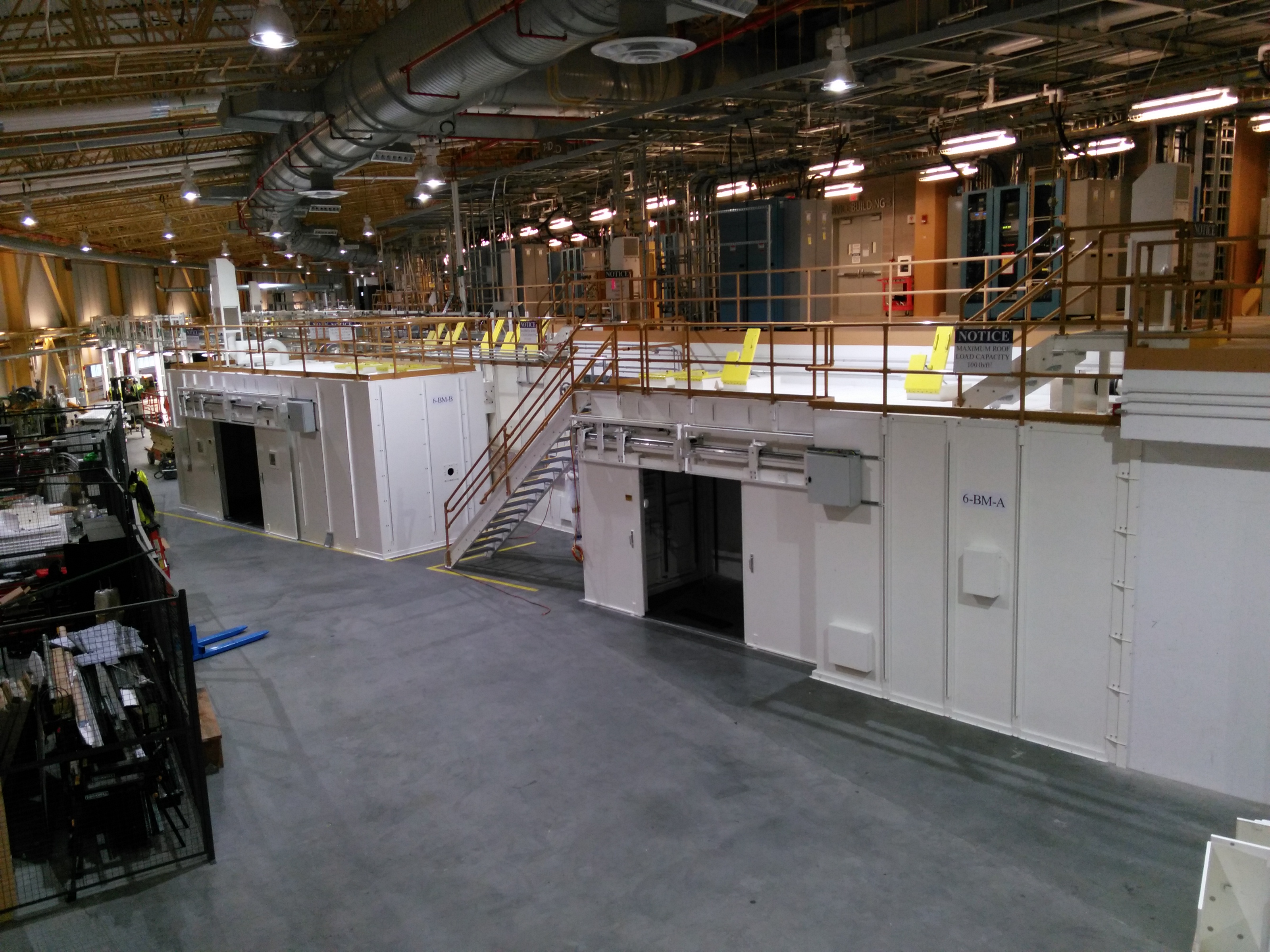
Figure 1: The finished hutches!
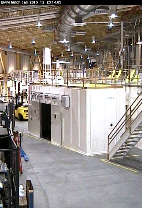
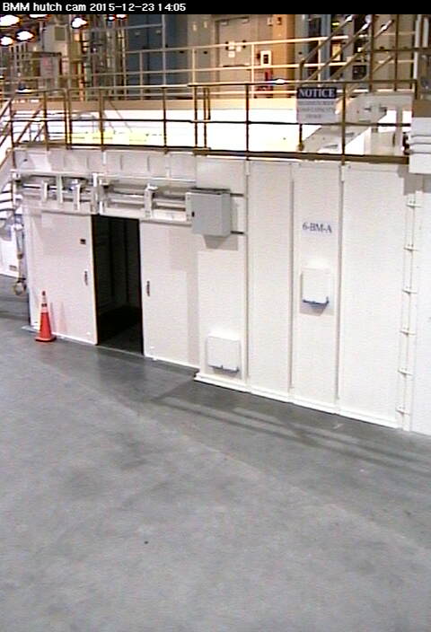
Hutch construction webcam images, December 23, 2015
| B hutch | A hutch |
 |
 |
Last hutch construction video (avi format, 9.6 MB). This includes snapshots from Nov 30 through Dec 7, 2015 and runs about 1 minutes 19 seconds. The soundtrack is a Yakety Axe, a Chet Atkins arrangement for steel guitar of Yakety Sax (which many know as the Benny Hill theme). This music is in the public domain.
May 19 2017
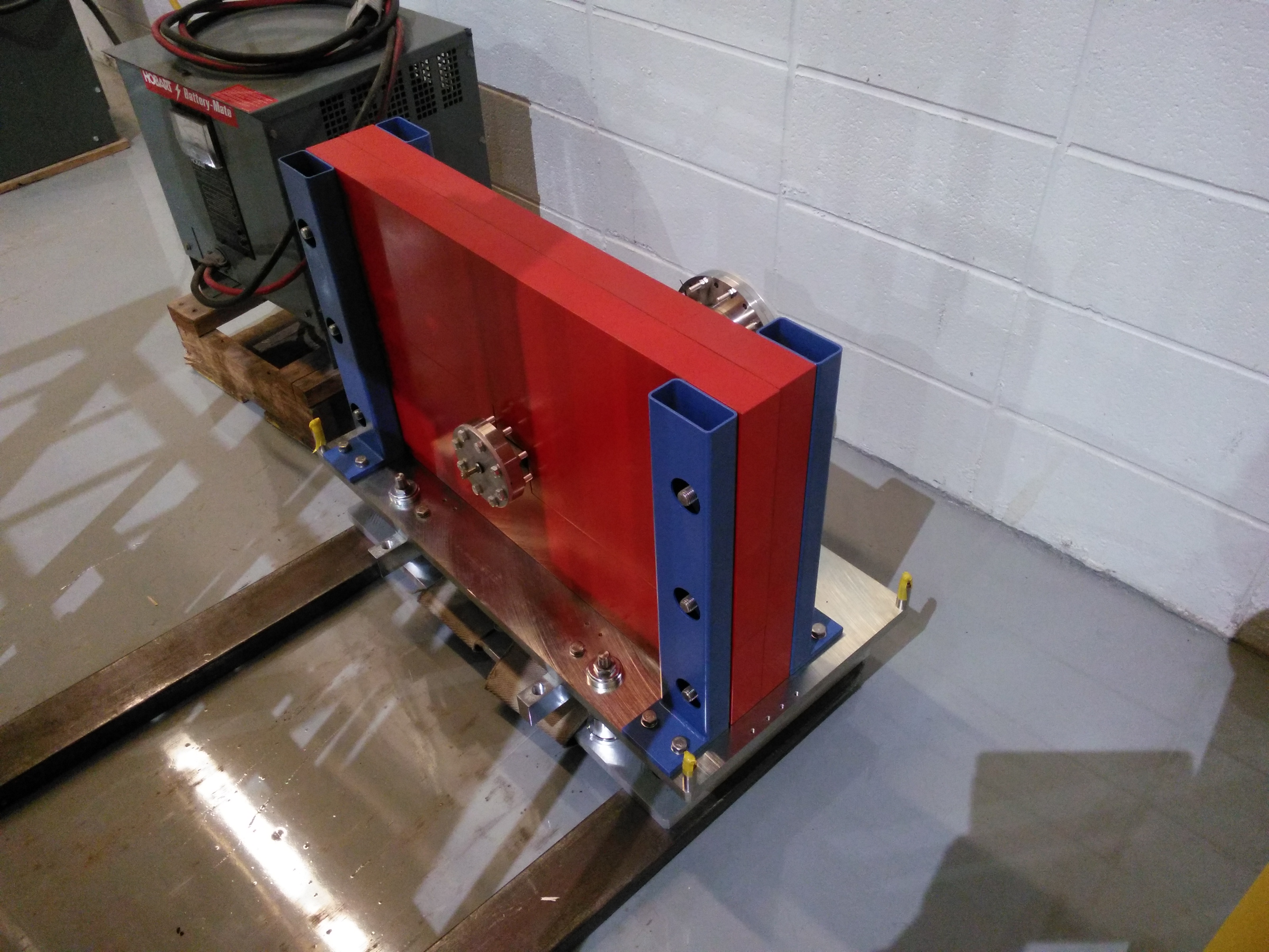
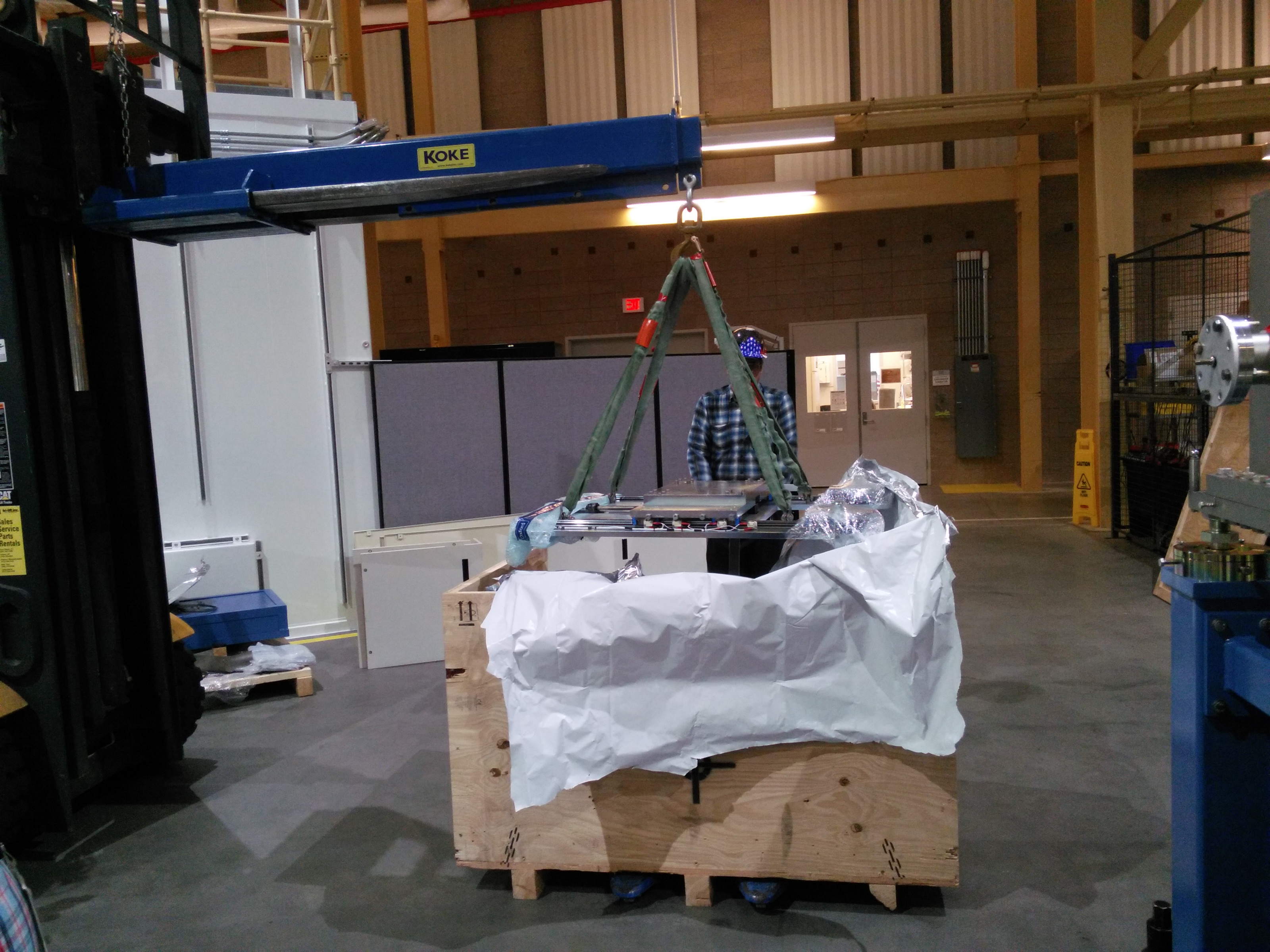
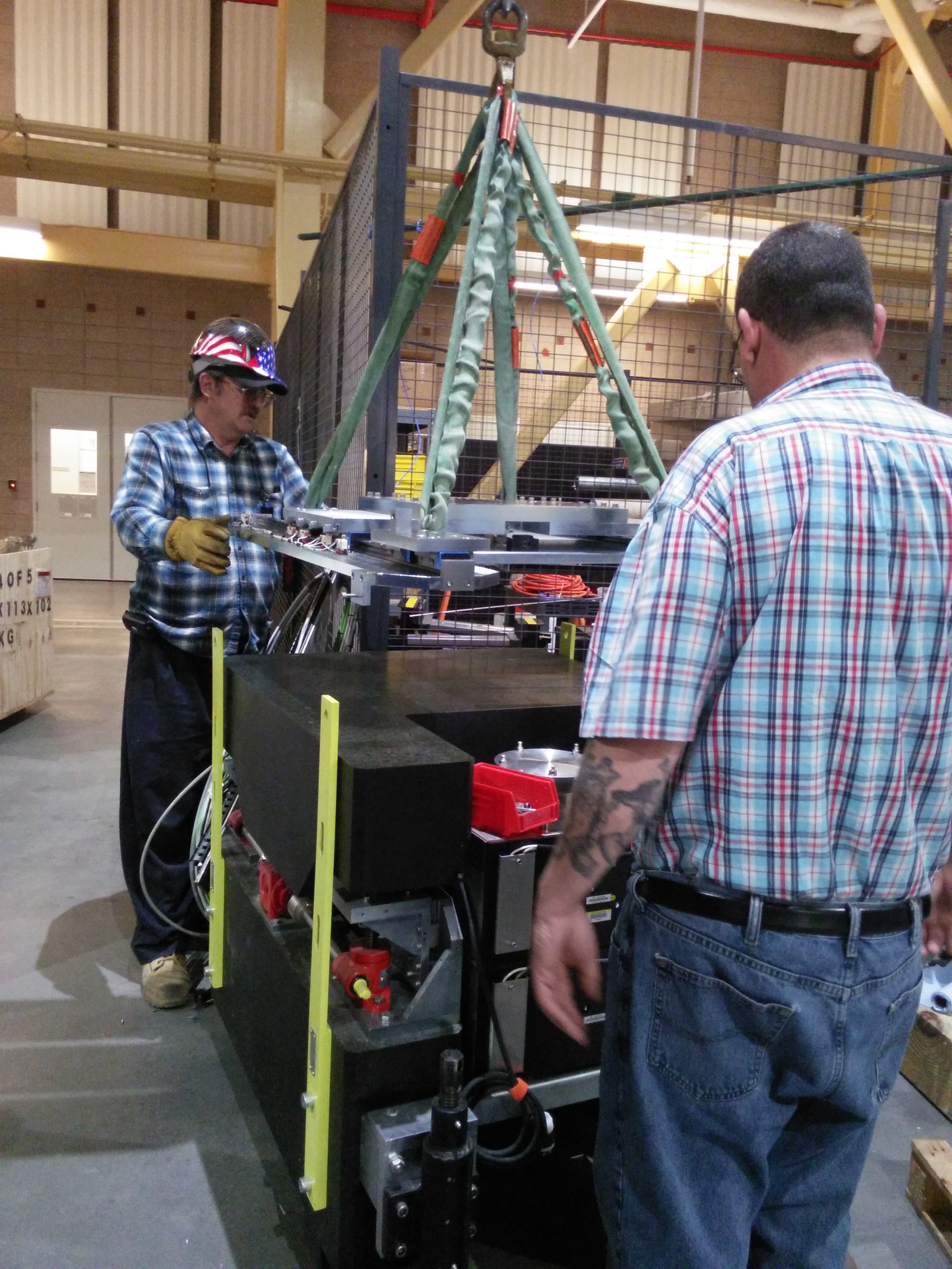
Today's big event was the unpacking and assembling of the optic for the focusing mirror (M2).
| The crate containing the optic and bender from SESO | M2 with the lid off, looking upstream | M2 with the lid off, looking downstream | The lid from M2, sitting on the floor |
 |
 |
 |
 |
The mono crystal cage was moved into position before work on M2 began.
| Hoisting the crystal cage around M2 | Fitting the cage onto the mono Bragg axis |
 |
 |
Prepping the mounting platform for the bender and optic….
| The mounting platform, removed from M2 | The actuators and kinematic mounts on M2 | Close-up of the downstream kinematic mounts |
 |
 |
 |
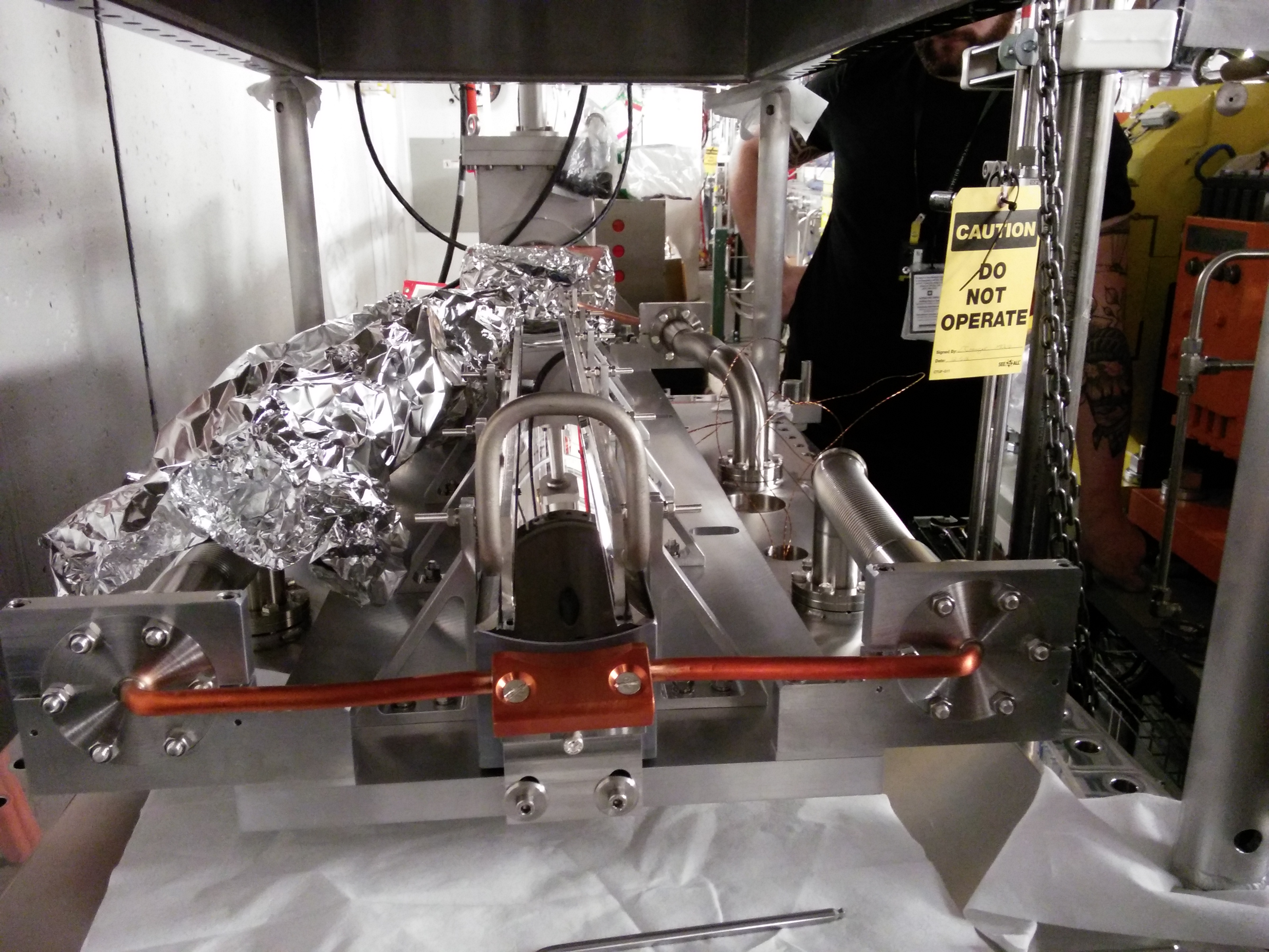
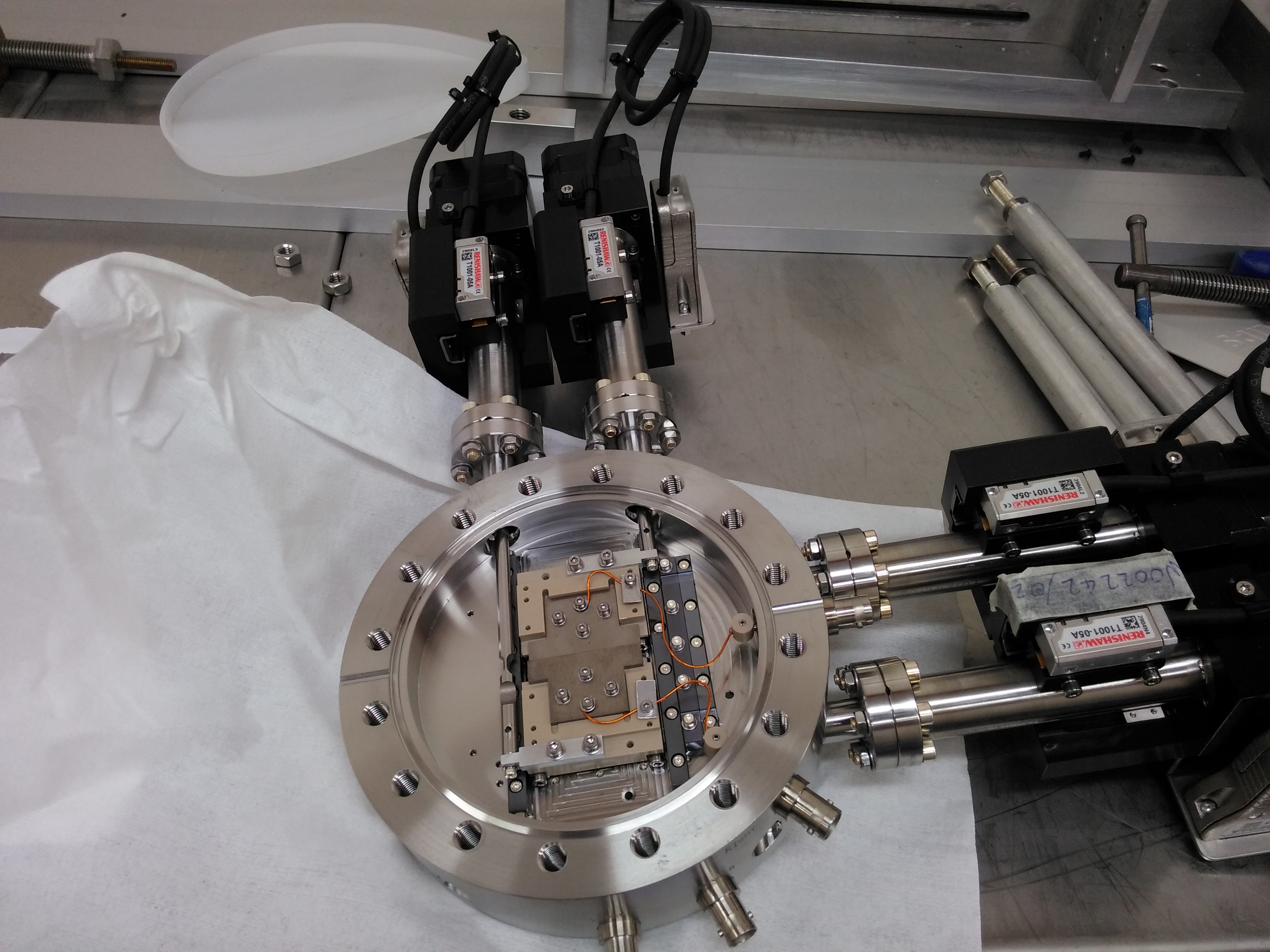
A few hours later, Beau had the bender assembled and the optic in place. This is now ready for survey.
| M2 bender and optic, looking downstream | The downstream end of the bender | The upstream end of the bender | Looking upstream |
 |
 |
 |
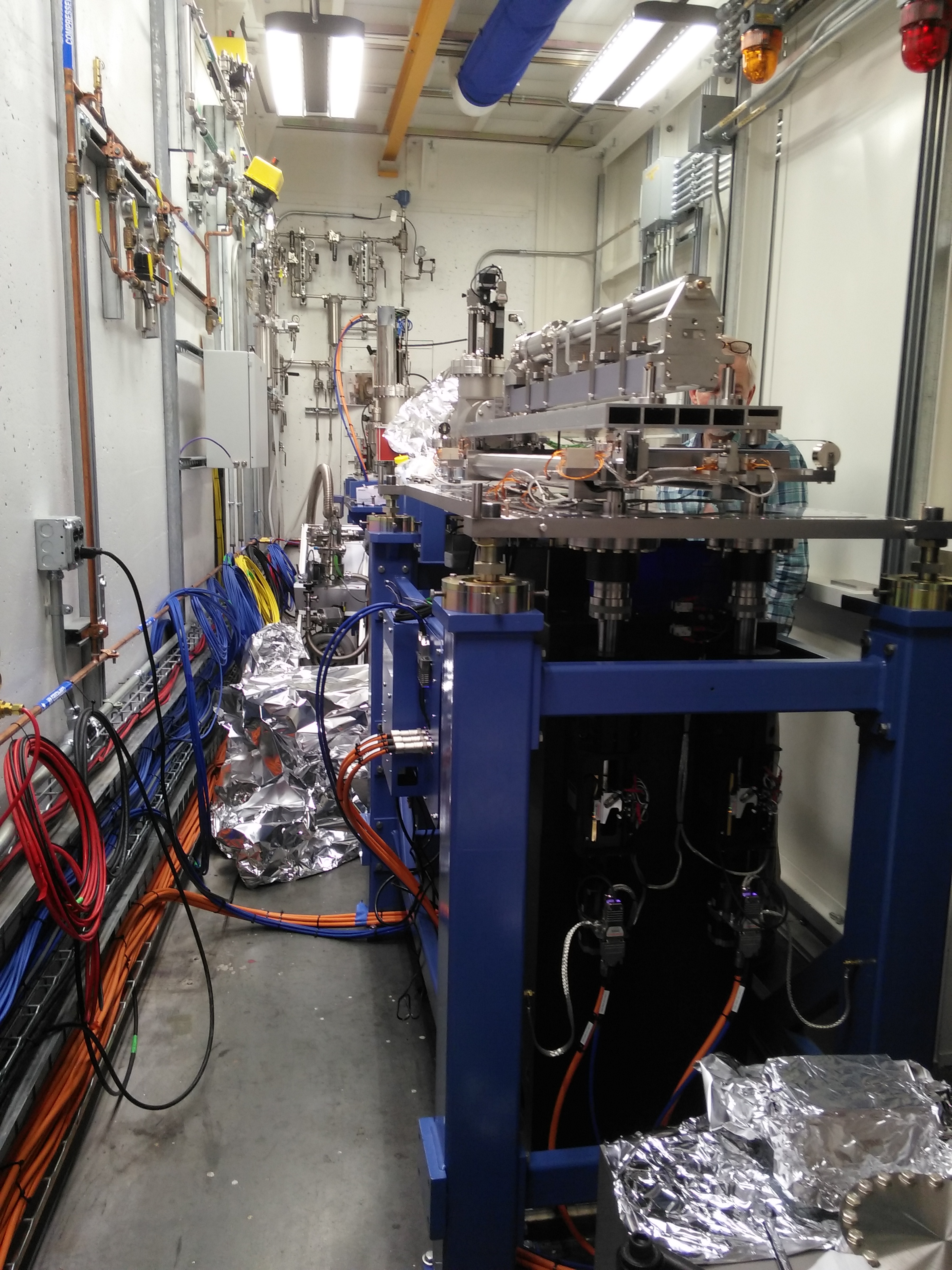 |
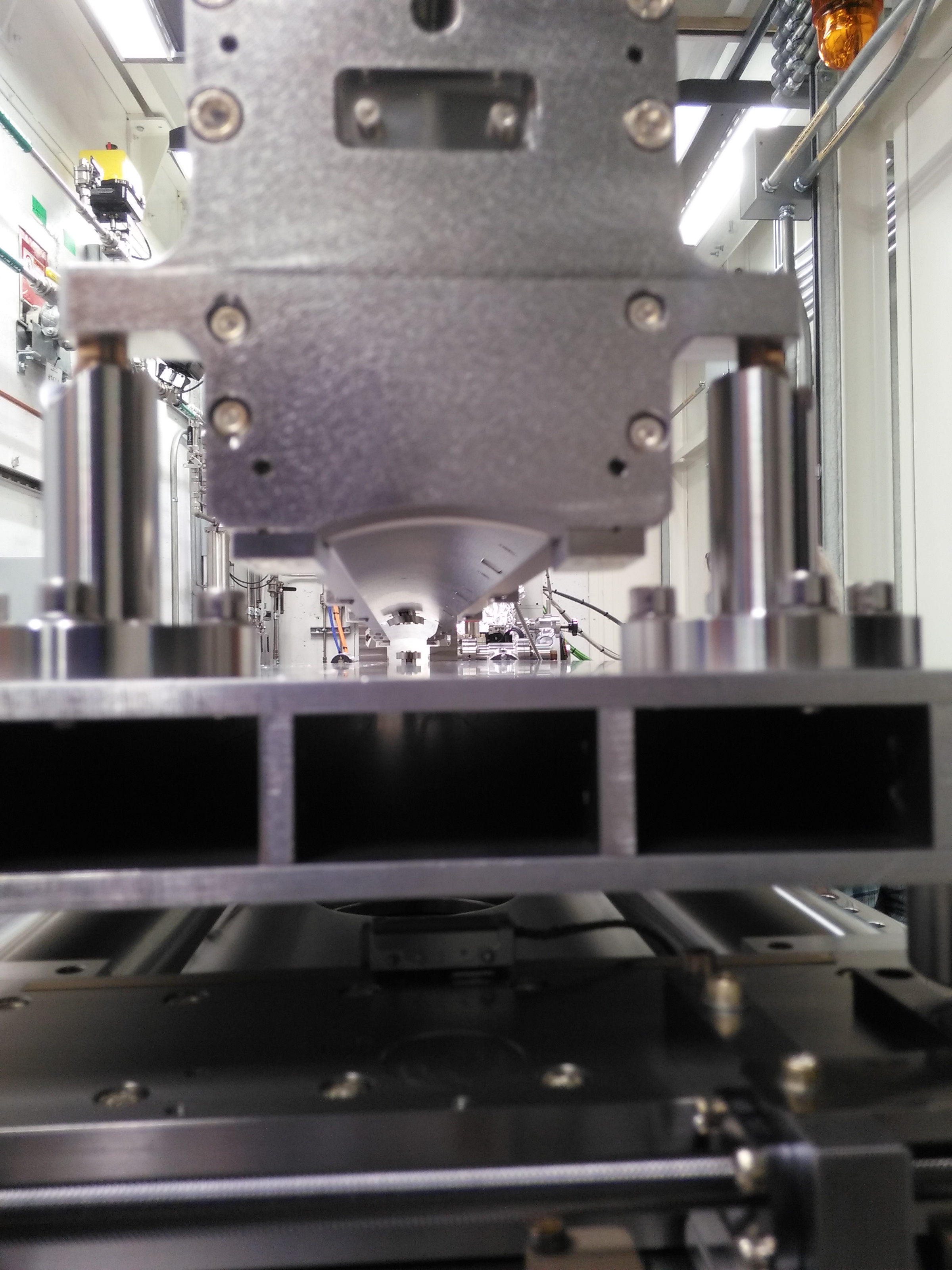
Figure 2: From downstream, peering up at the reflecting surface of M2.
May 17 2017
Today the second diagnostic module (DM2) and the focusing mirror (M2) were installed.
| M2, looking upstream, DM1 in the background | Another view upstream, with the mono | DM2 | Looking downstream at DM2 and M2 |
 |
 |
 |
 |
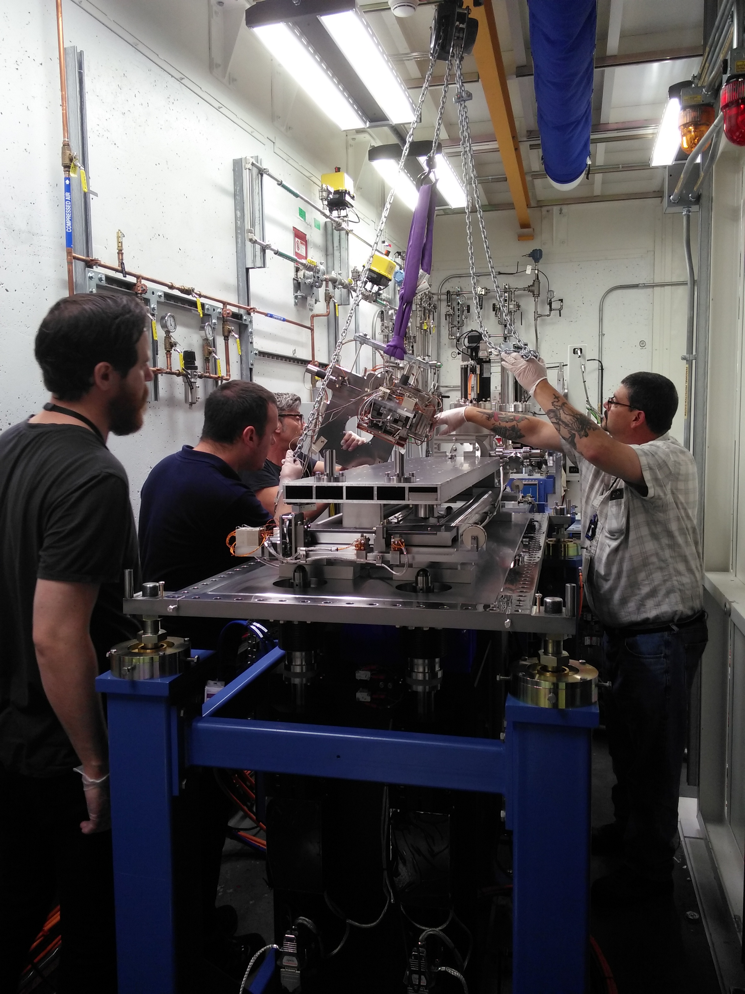
May 16 2017
Today there has been some nice progress towards installation. Much of it is not very photogenic, but a lot is getting done.
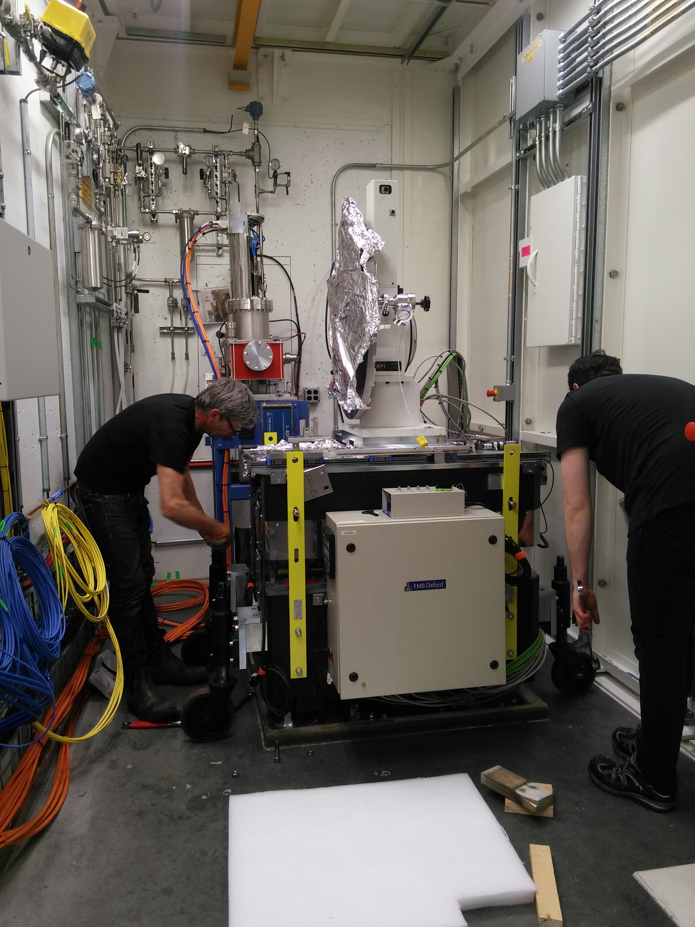
In the first photo, Ian and Beau are lowering the mono off its wheels and onto its grouted plate.
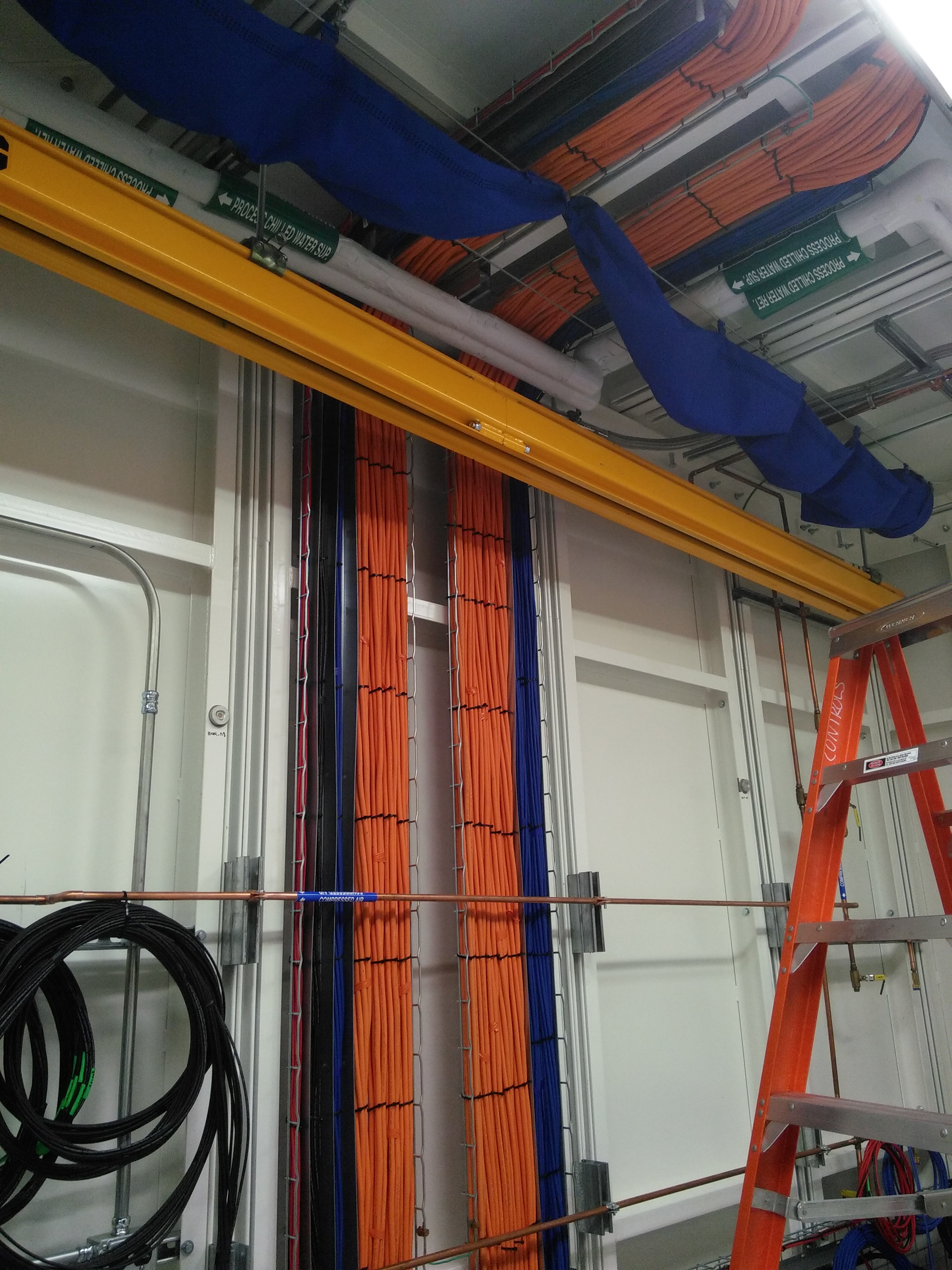
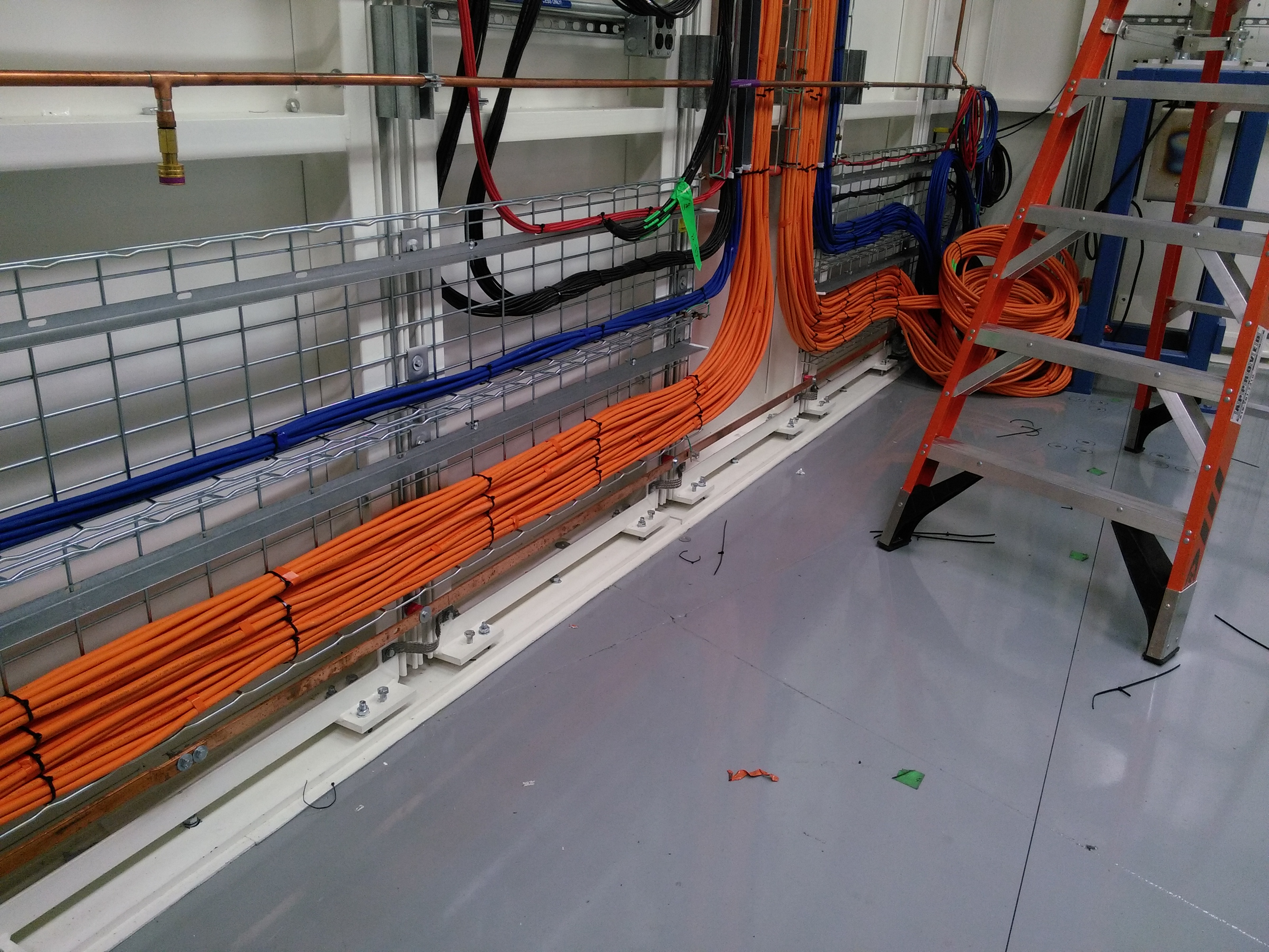
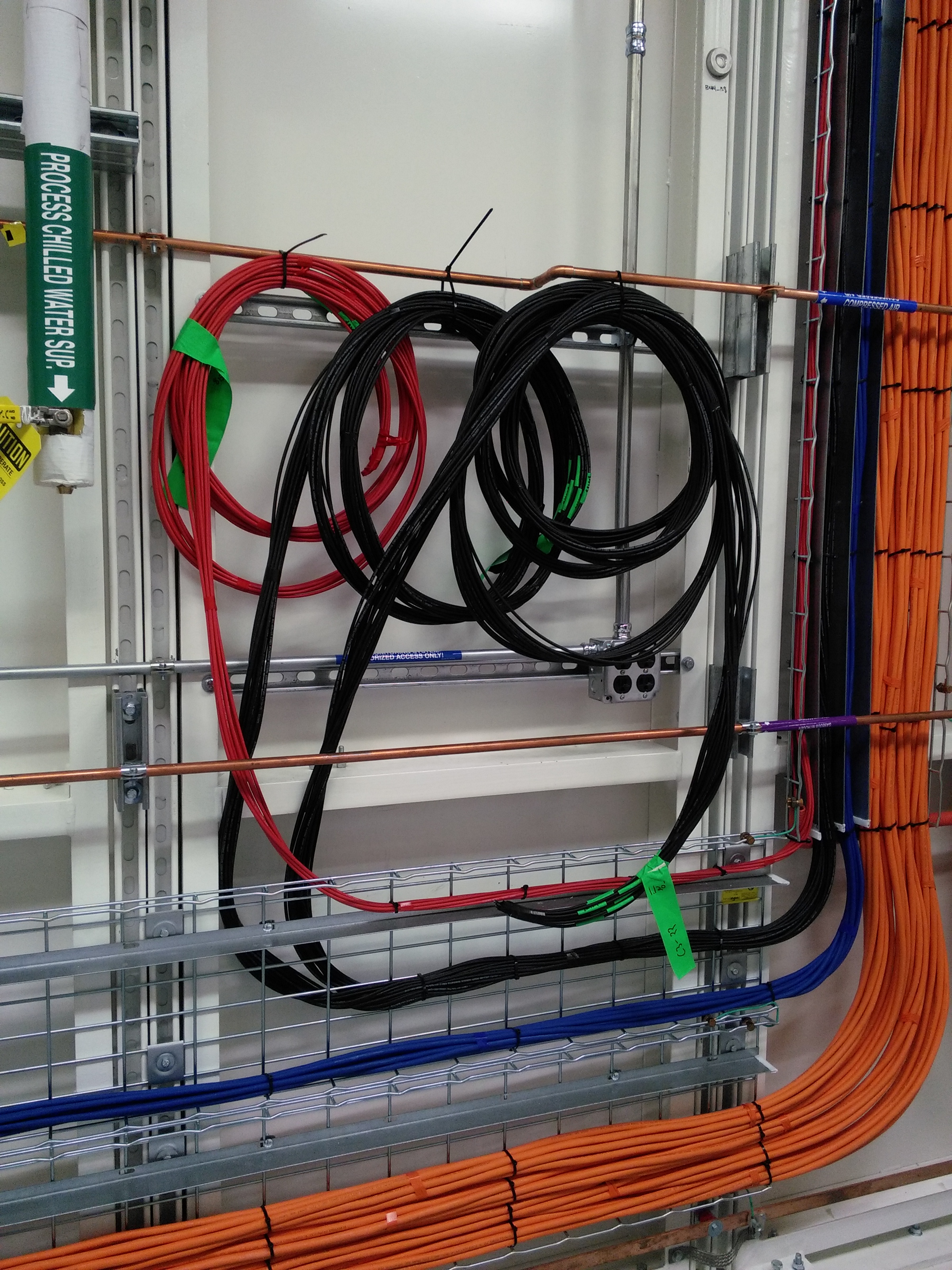
| The mono is back in its home. Note DM1 just upstream | Travis is mostly done with cable pulling in the B hutch | Cables going upstream tothe XAS table | Signal and SHV cables |
 |
 |
 |
 |
| The filter assembly from DM1 | Filter assembly, up close | The Bremsstrahlung shield stand, installed |
 |
 |
 |
May 15 2017
Diagnostic module #1
After some leak checking and driving the various actuators, it seems as though DM1 survived its tumble last week. Amazing!
| DM1, installed in the A hutch | The guts of the filter assembly actuators | The guts of the cooled fluorescent sc reen actuator |
 |
 |
 |
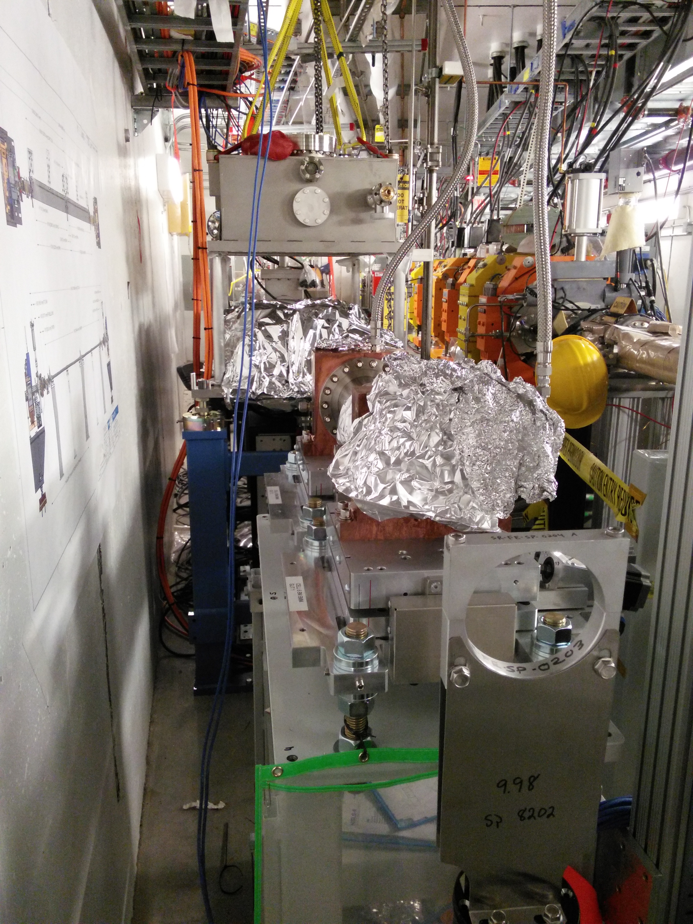
Bremsstrahlung shield
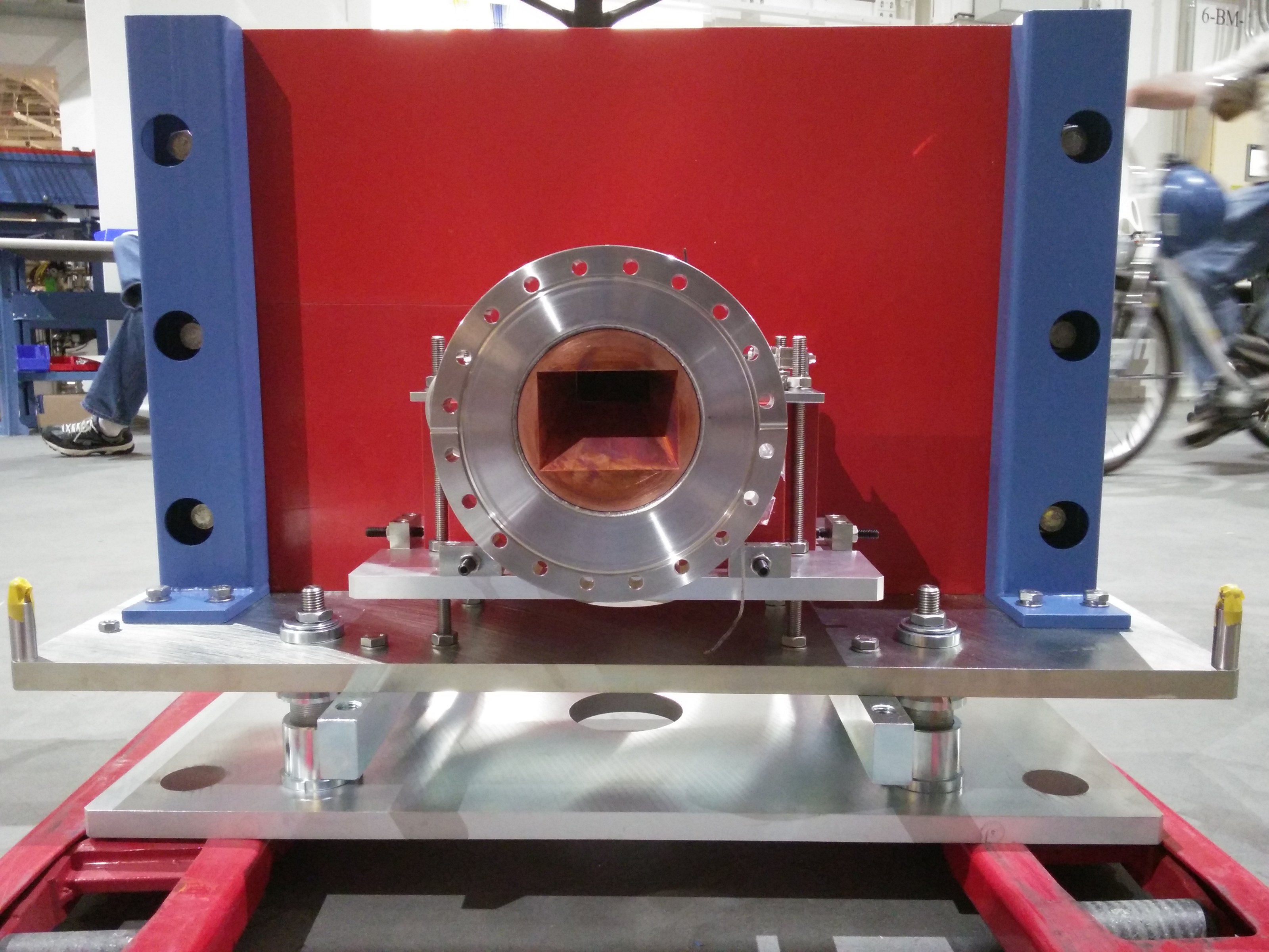
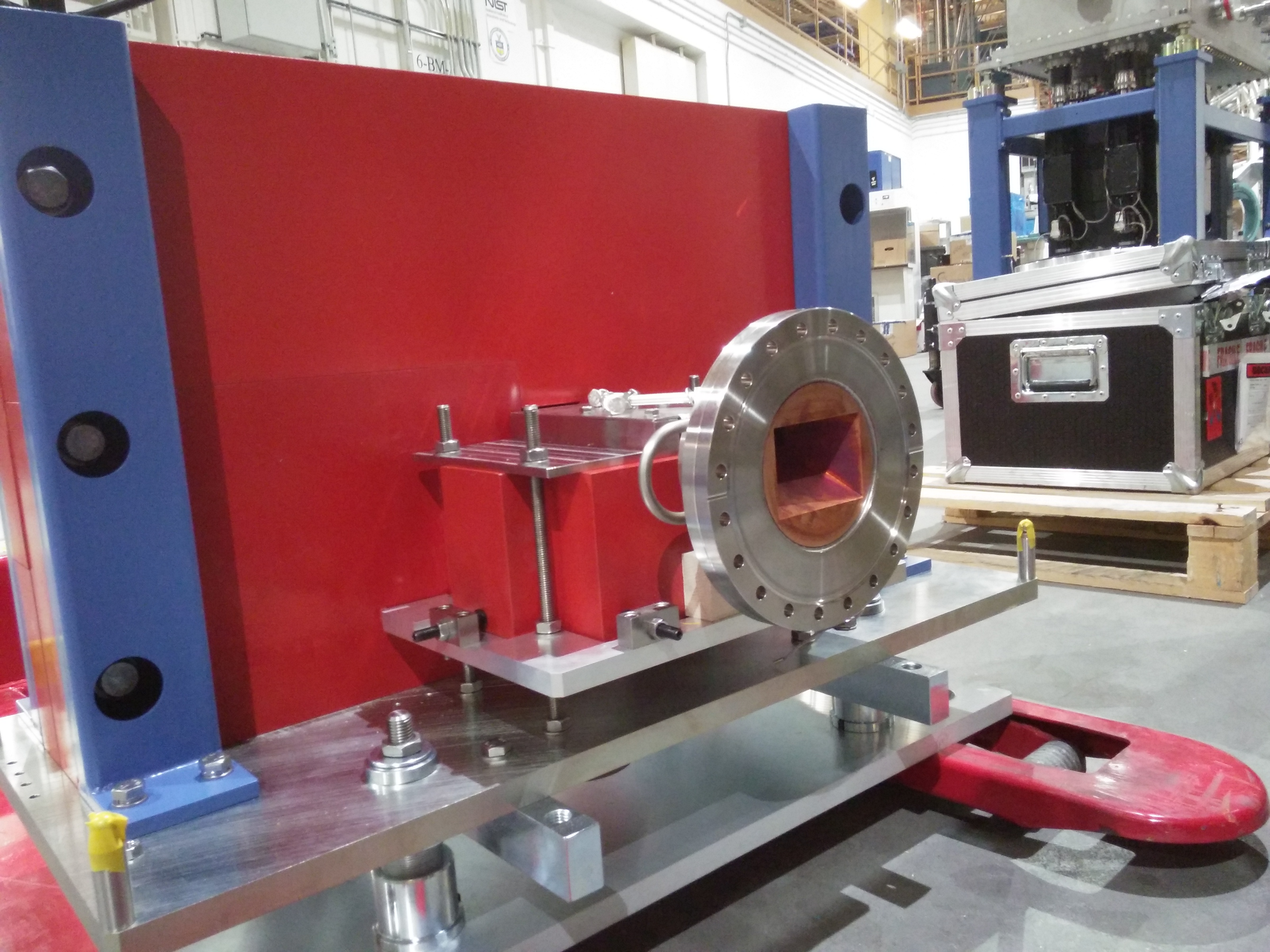
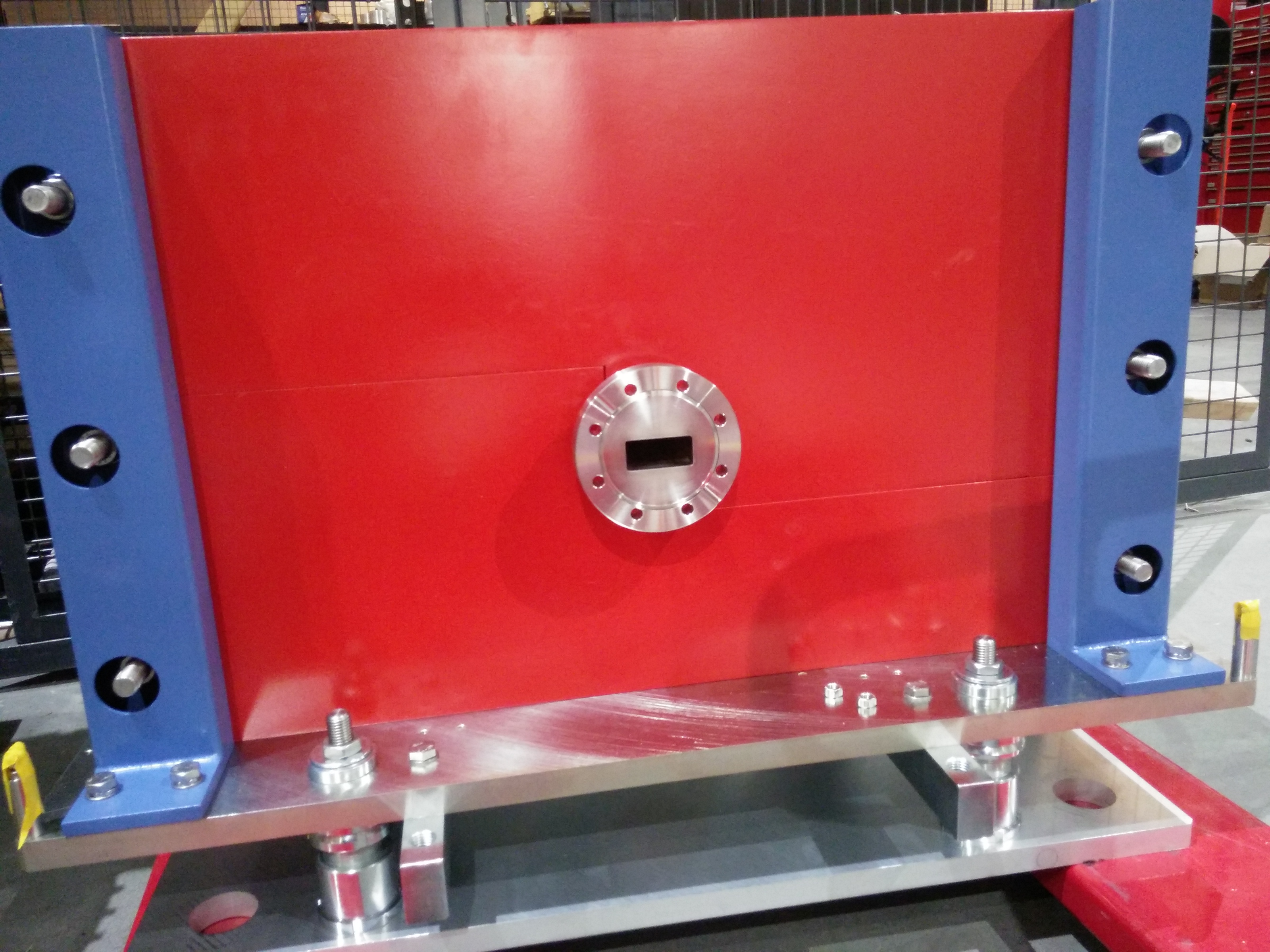
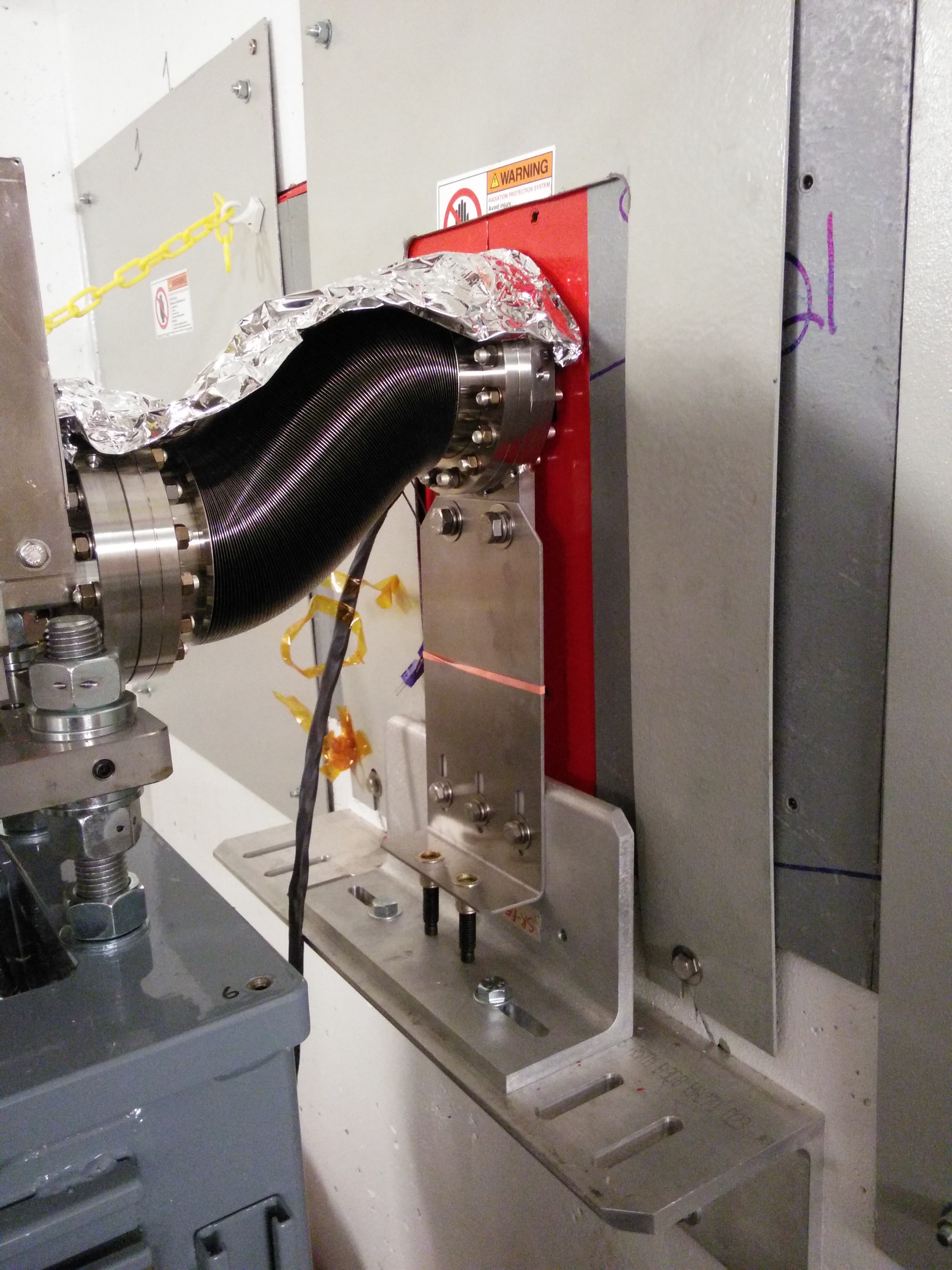
The Bremsstrahlung shield stand is the next component after the monochromator. Before it was picked up from the floor after last week's delivery accident, the shielding parts were removed from the stand. What you see below is the shielding, sitting on a pellet jack, waiting from installation.
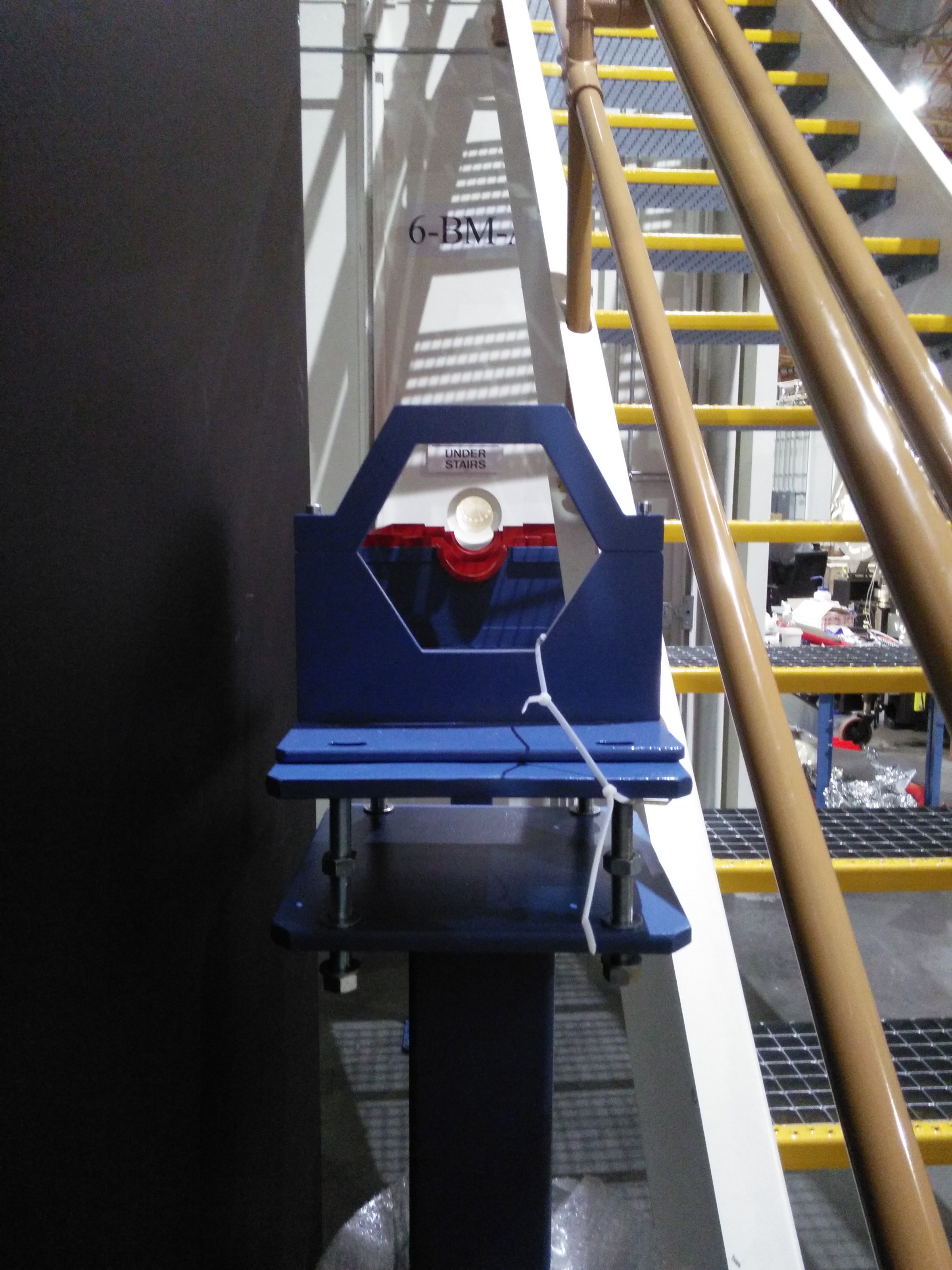
A new problem crops up. Notice below that the pink beam stop (the copper piece with the hole for the beam to pass through) is offset from the center of its flange. The flange was welded in place rotated by 180 degrees. The radiation safety bits are in the correct location, but the flange is offset in the wrong direction. This means that additional strain will be placed on the bellows connecting this to the monochromator.
The primary Bremsstrahlung shield is the thick, red-painted, lead block just below the beam pipe. The purpose of this component is to stop the high-energy gas Bremsstrahlung originating in the storage ring. Because we have an upward-deflecting mirror in the front-end, the pink synchrotron light enters the hutch above the primary Bremsstrahlung. Hence the primary Bremsstrahlung shield is below the X-ray beam path.
The copper bit is the pink beam stop. It's purpose is to stop the pink beam from t he front end mirror in the situation where the first monochromator crystal is, for some reason, removed from the beam. It is water-cooled – note the cooling line brazed into the copper and sticking out in the foreground.
The big red mass of lead is secondary Bremsstrahlung shield #2. The purpose of this is to catch Bremsstrahlung radiation which has scattered off of some component upstream, either in the A hutch or in the front end. Its large area is necessary to catch the full possible fan of such a scattering event.
| The pink beam stop | The primary Brem shield and secondary Bram shield #2 | The downstream exit of the Bremsstrahlung shield |
 |
 |
 |
May 12 2017
Picking up the pieces
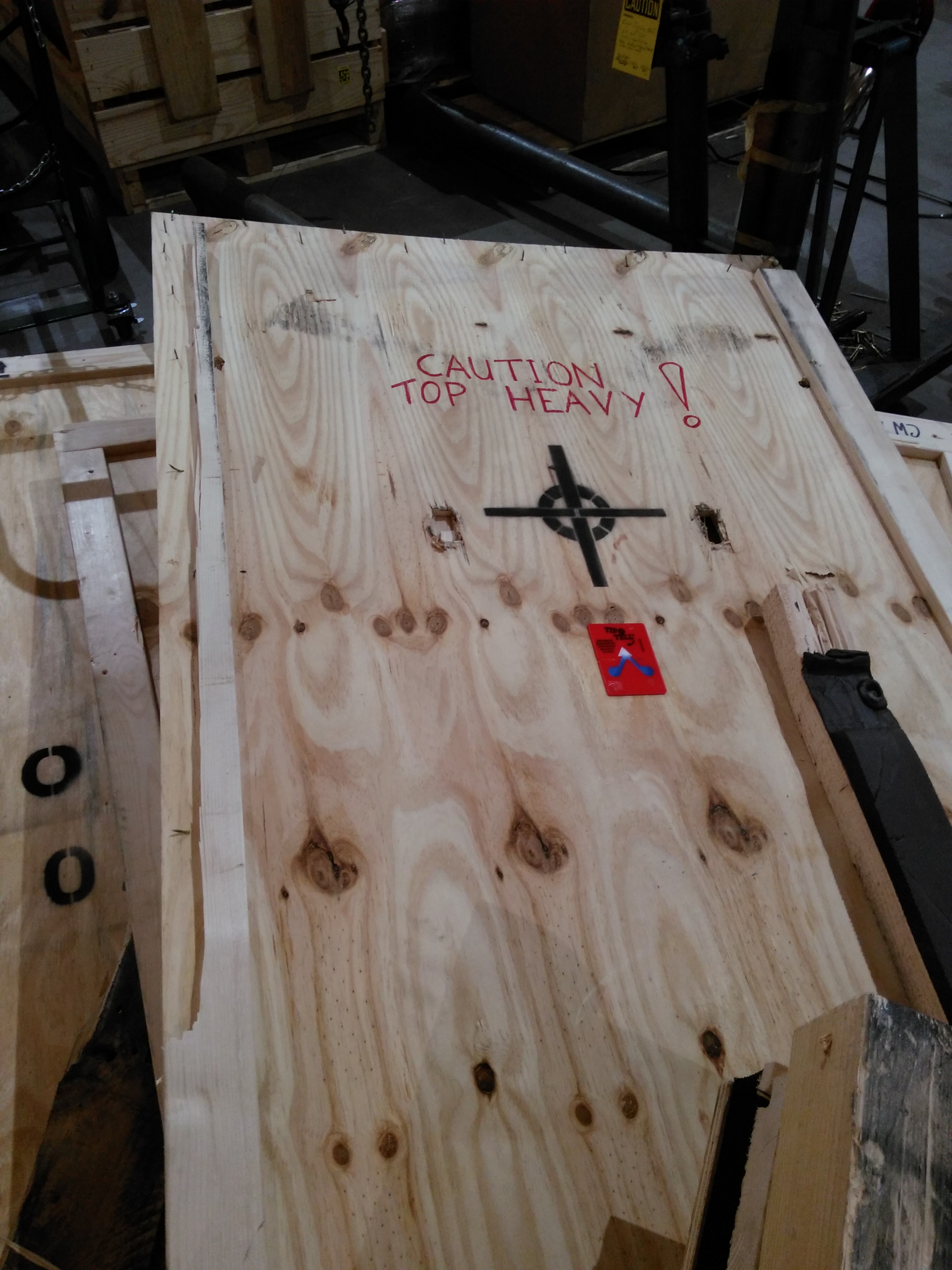
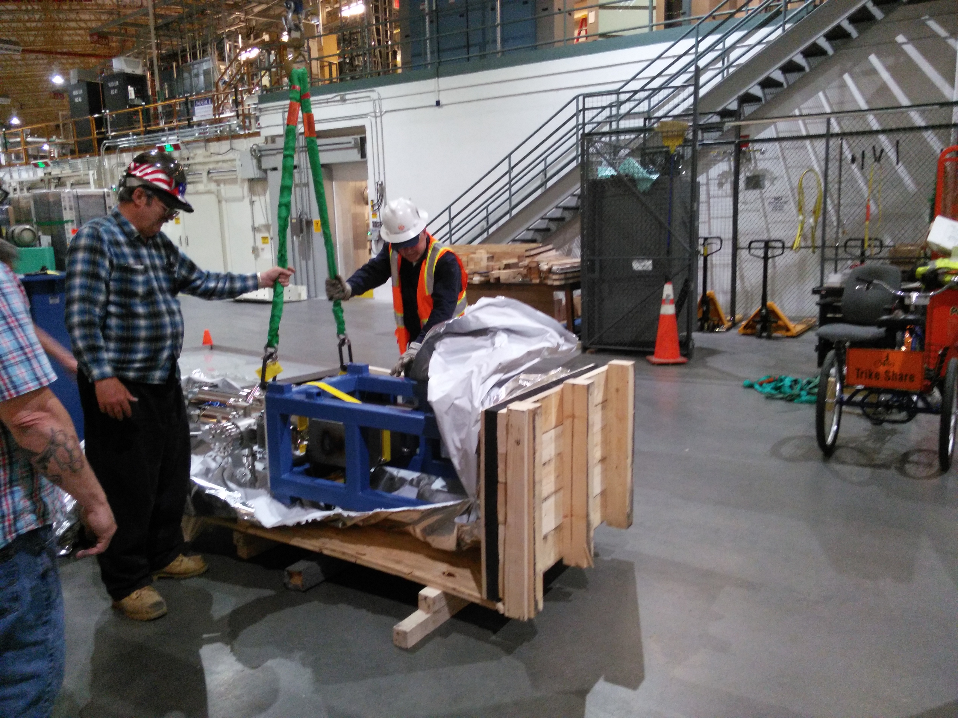
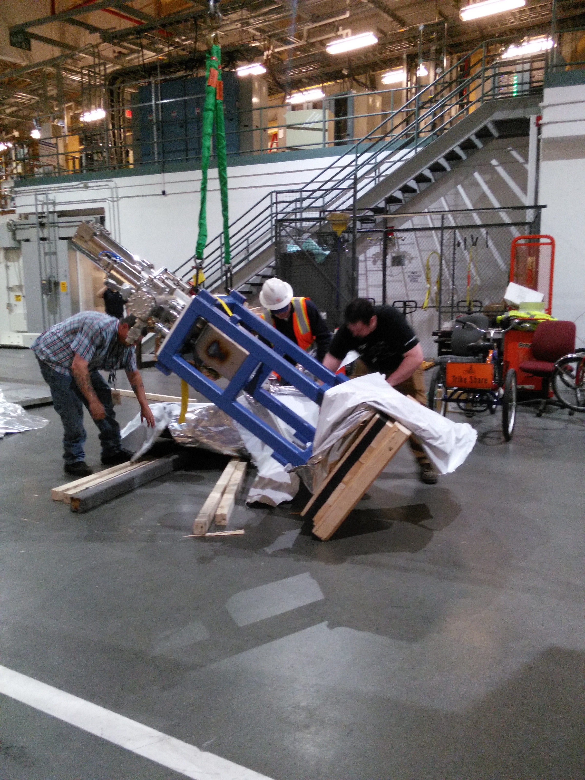
On May 11, the first diagnostic module and the Bremsstrahlung shield stand were delivered, along with several crates of smaller kit. Unfortunately, the two large crates containing those components toppled over in the back of the delivery truck. Here is a photo journal of the work of the BNL riggers extracting that mess from the back of the delivery truck.
Today, the riggers came back to pick up all the components.
| The front side of the Brem crate showing the center of gravity | The Brem shielding, removed from its stand | The riggers begin lifting DM1 | Lifting … | More lifting … | Uh oh! The base is sliding along the floor… |
 |
 |
 |
 |
 |
 |
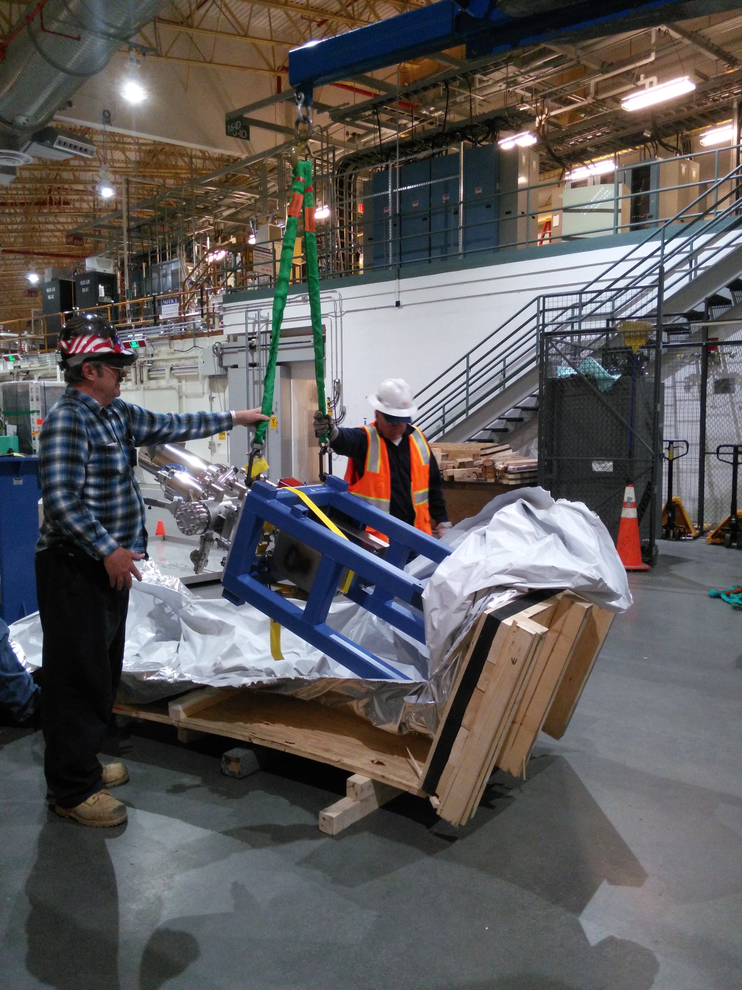
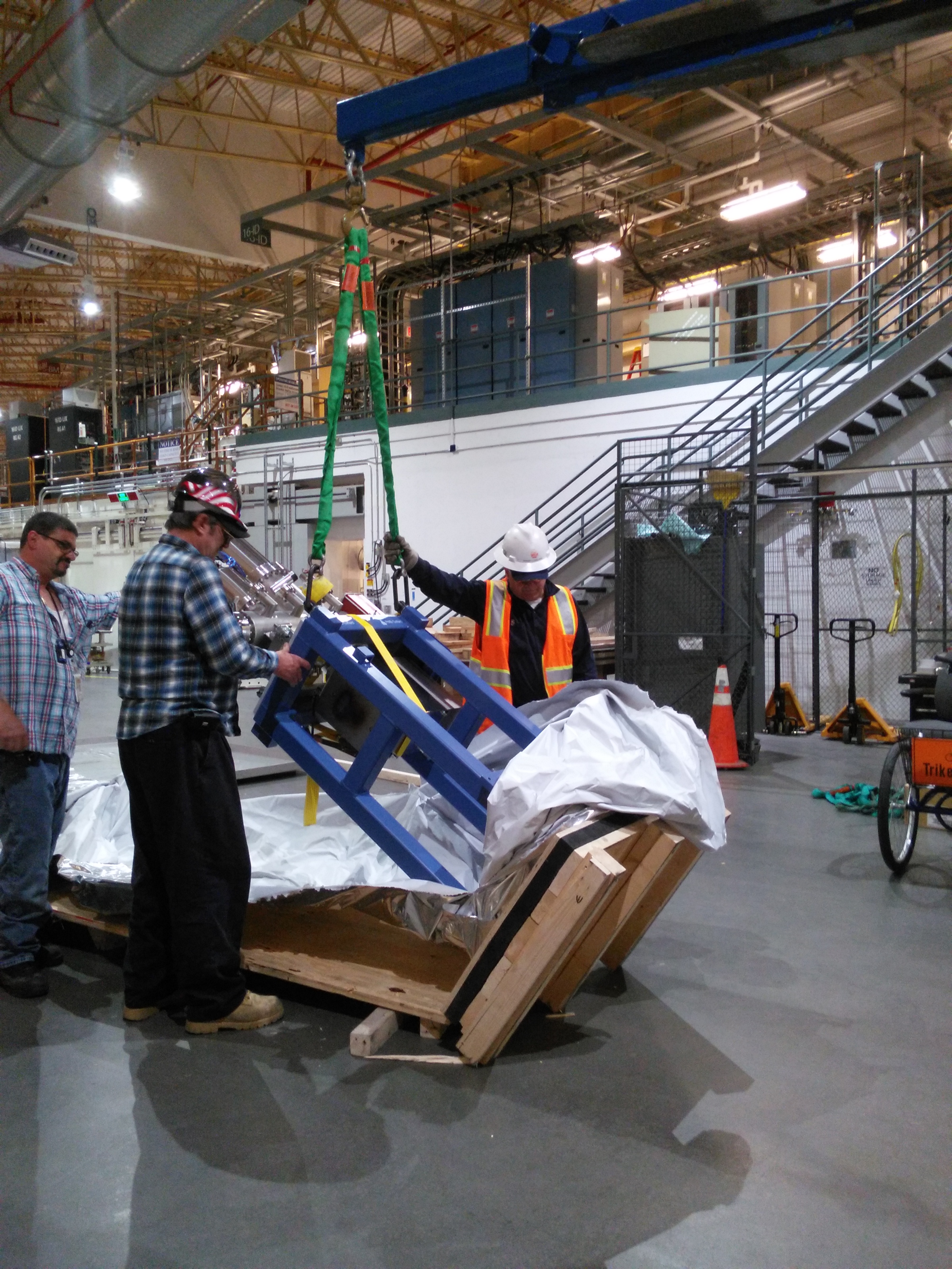
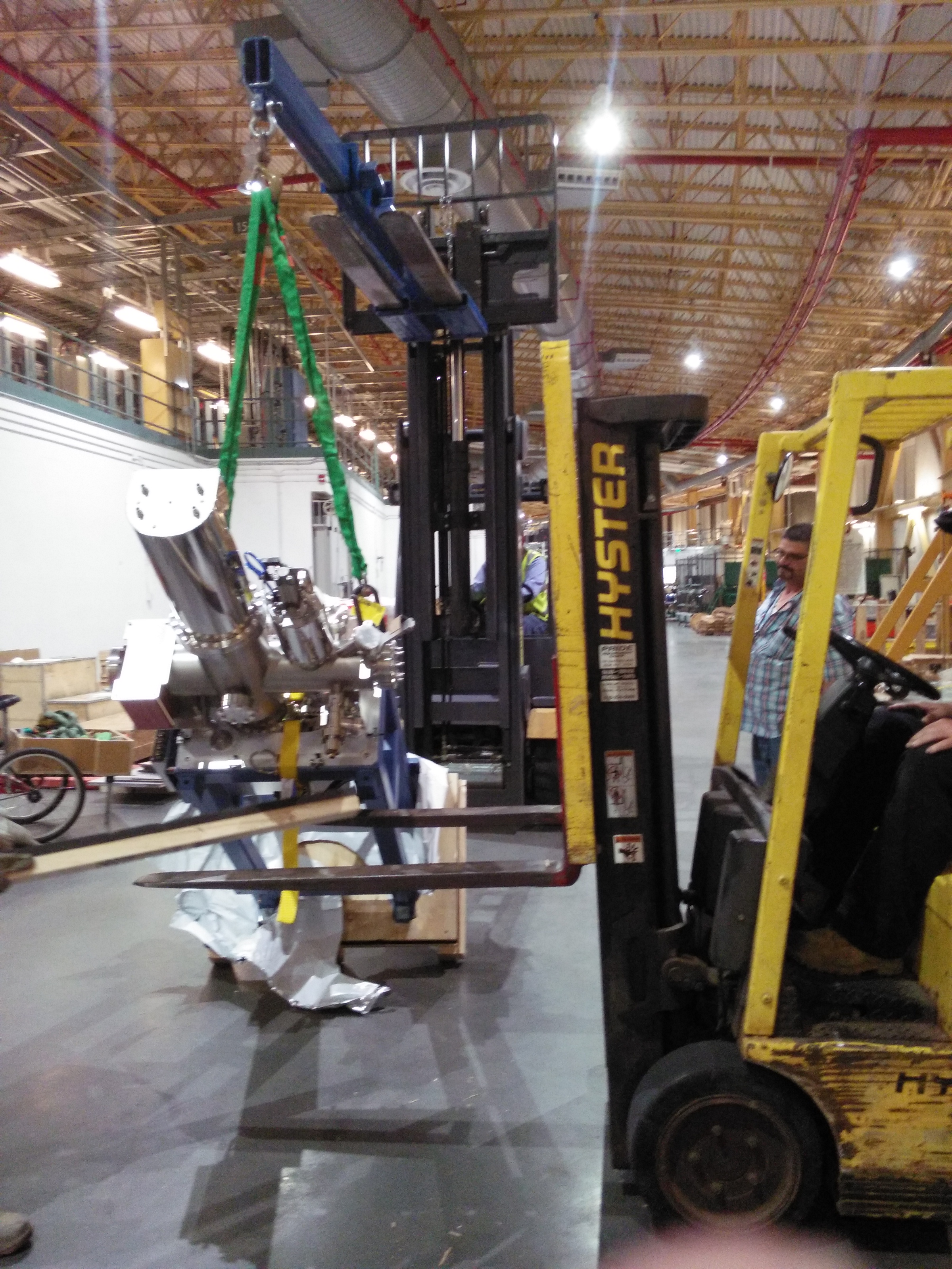
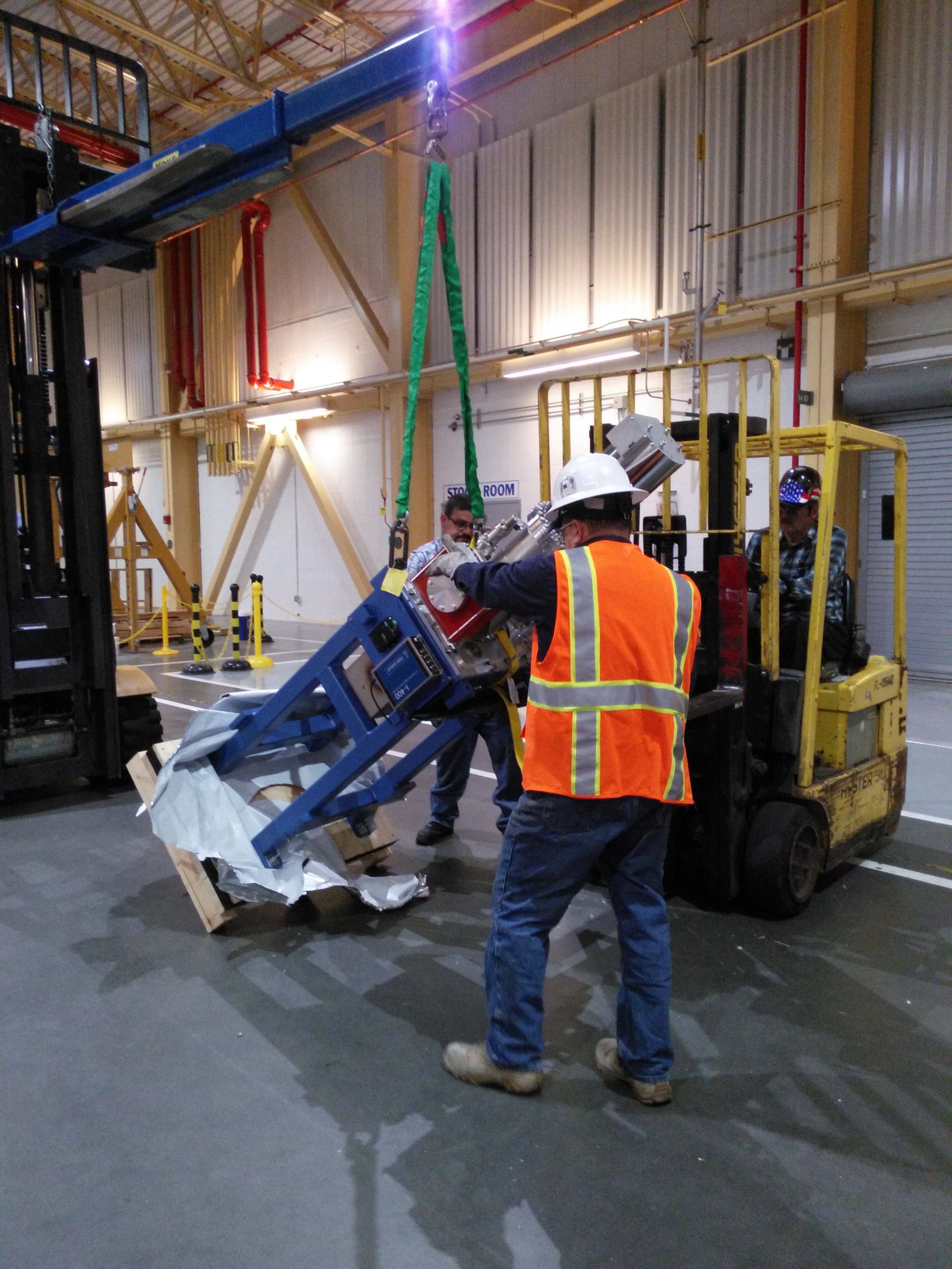
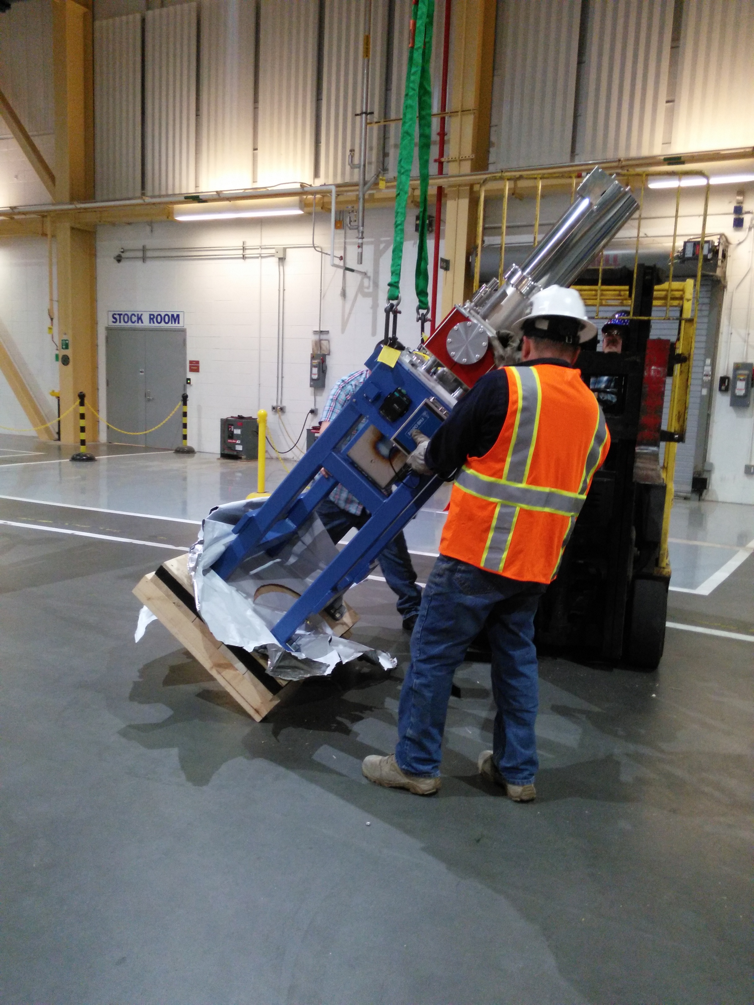
The solution to having DM1 slide along the floor was very clever. The BNL riggers are awesome!
| Use a second fork lift to lift from the other side | Up, up, up… | Getting there… | Almost up, pull, Jimmy, pull! | And up! | Whew! |
 |
 |
 |
 |
 |
 |
Other activities
The new mono plate allows the mono to be translated laterally between sets of Si(111) and Si(311) crystals.
I love the photo of M3. It looks like a real beamline!
| Secondary Bremsstrahlung shield #1 (on DM1) | Lifting the new mono plate out of the crate | Laying the new plate on the granite plinth | Mirror M3, temporarily in place for cable fitting |
 |
 |
 |
 |
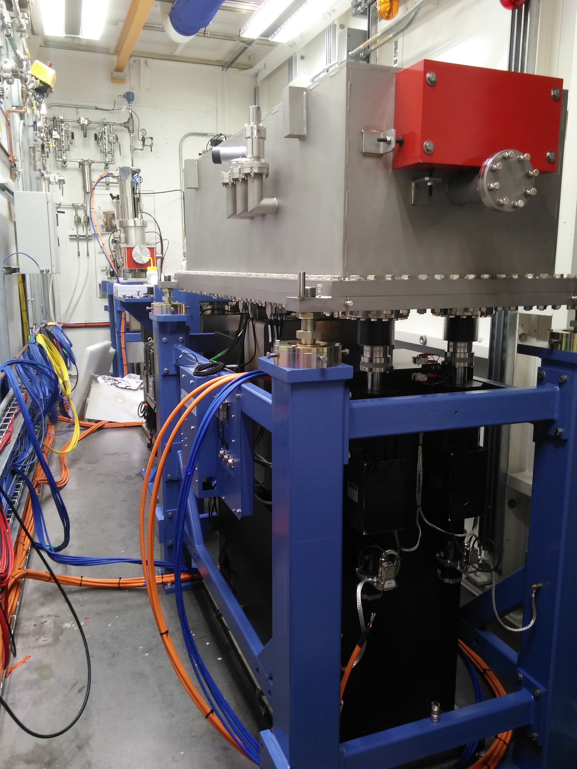
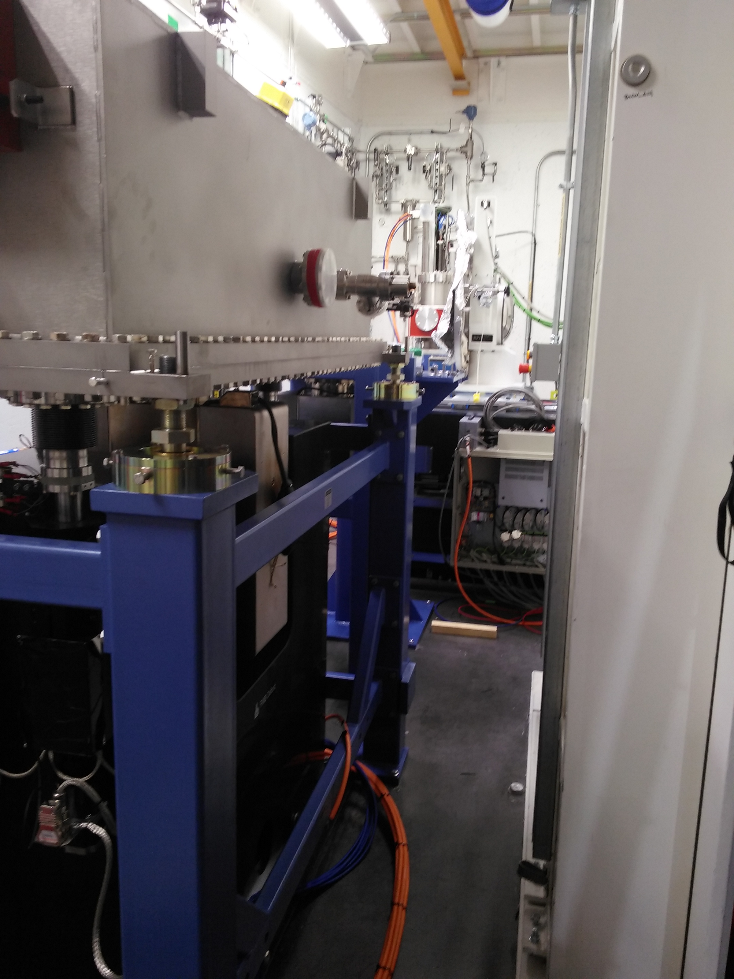
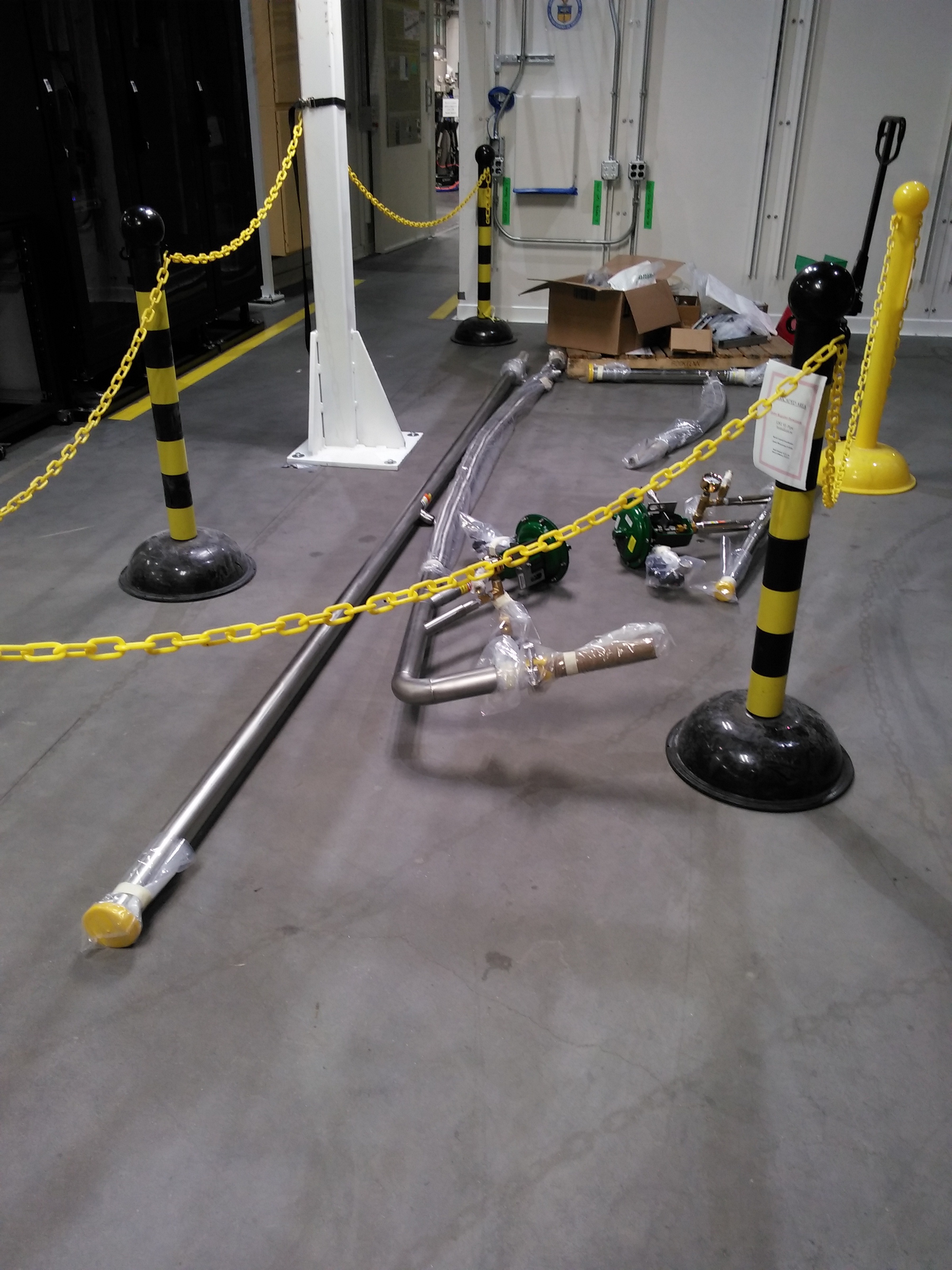
May 10 2017
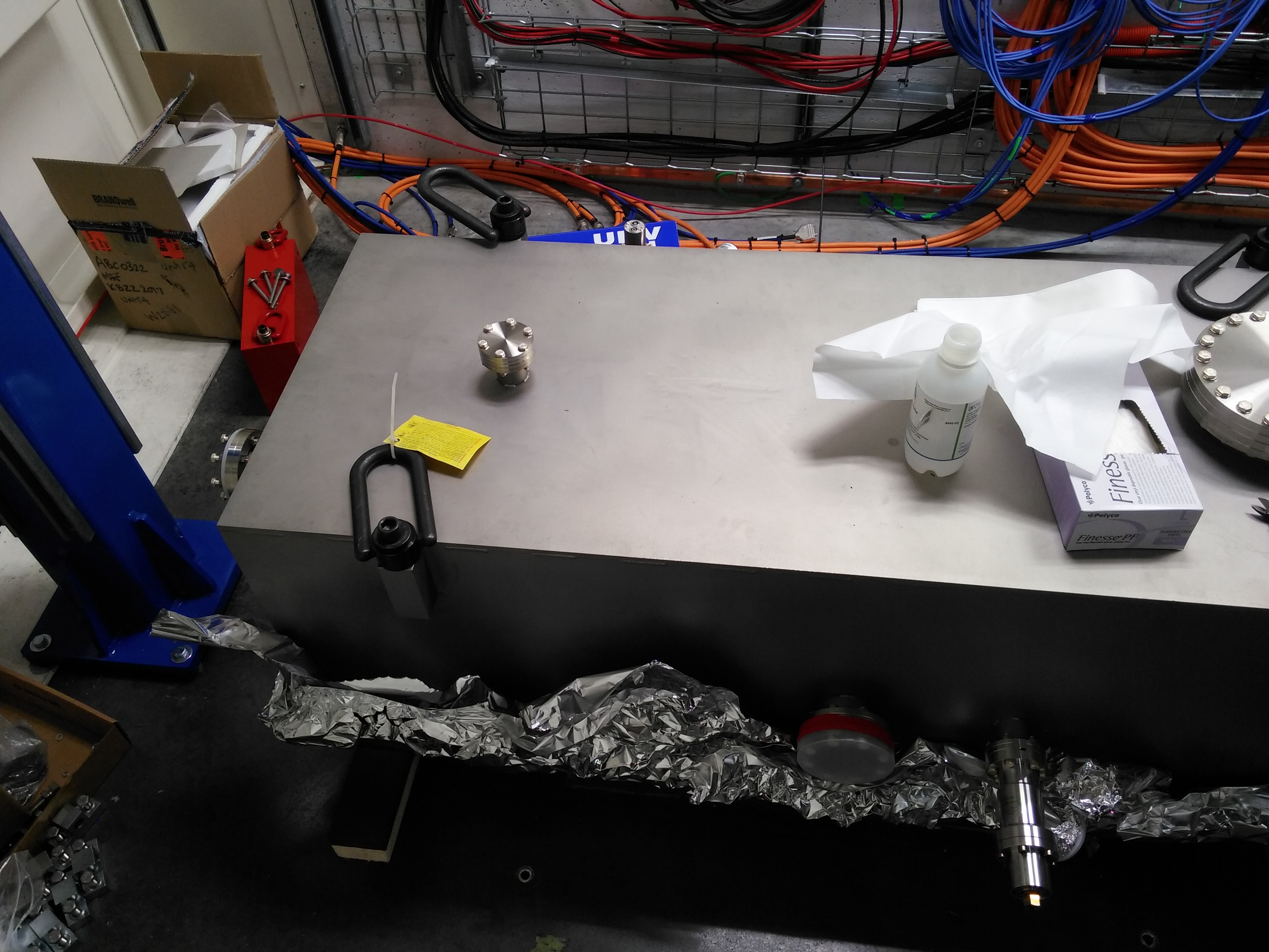
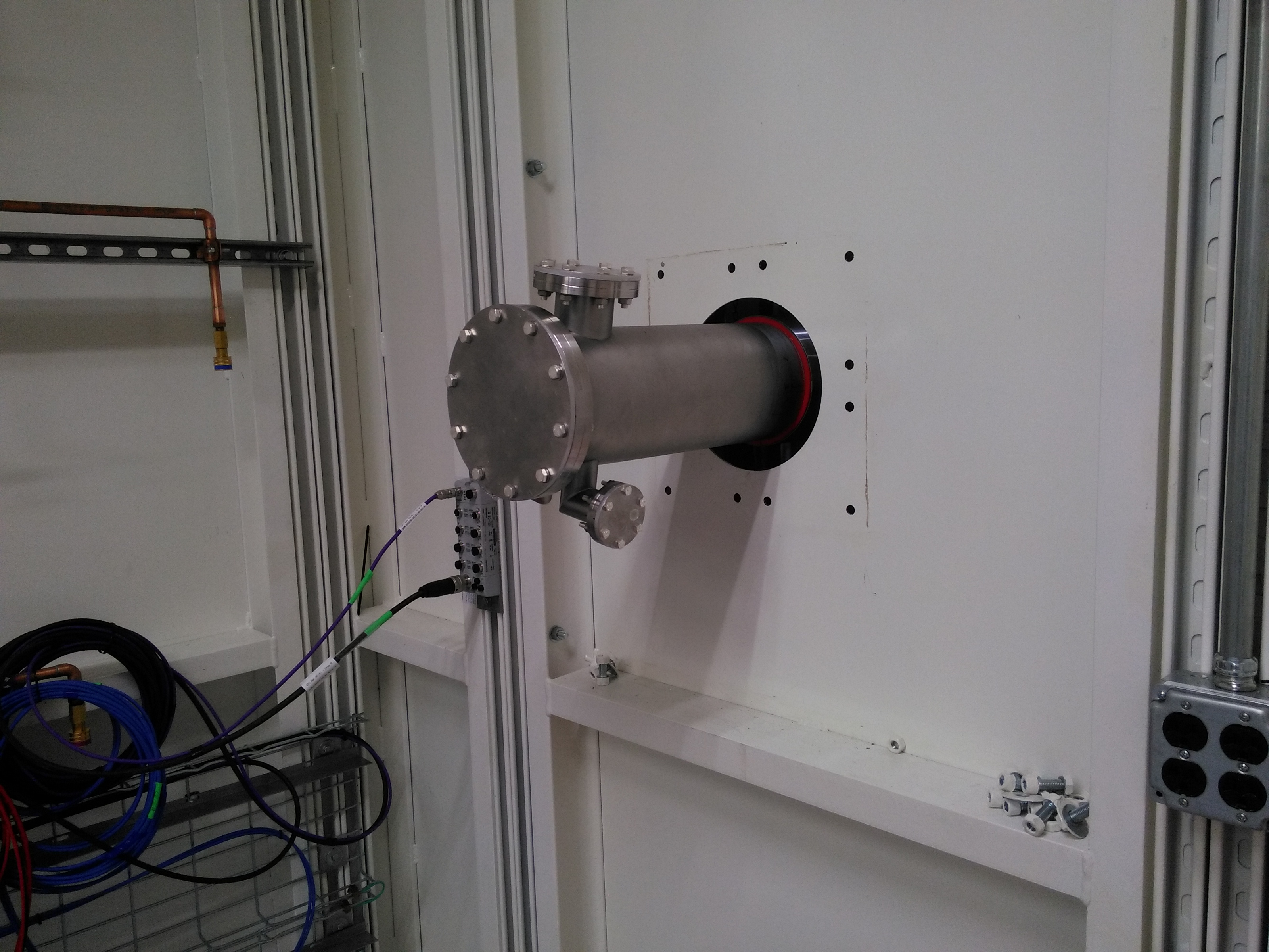
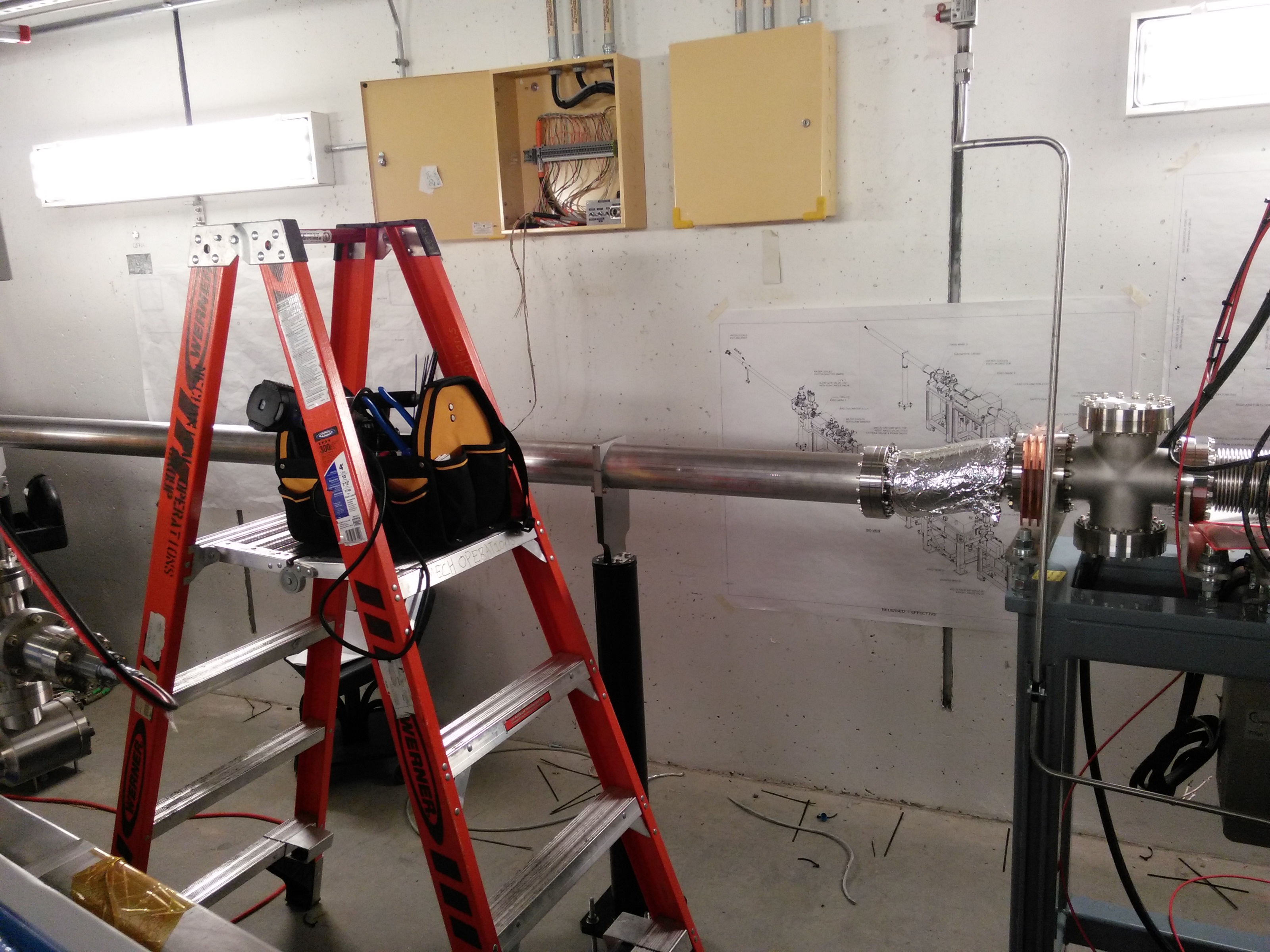
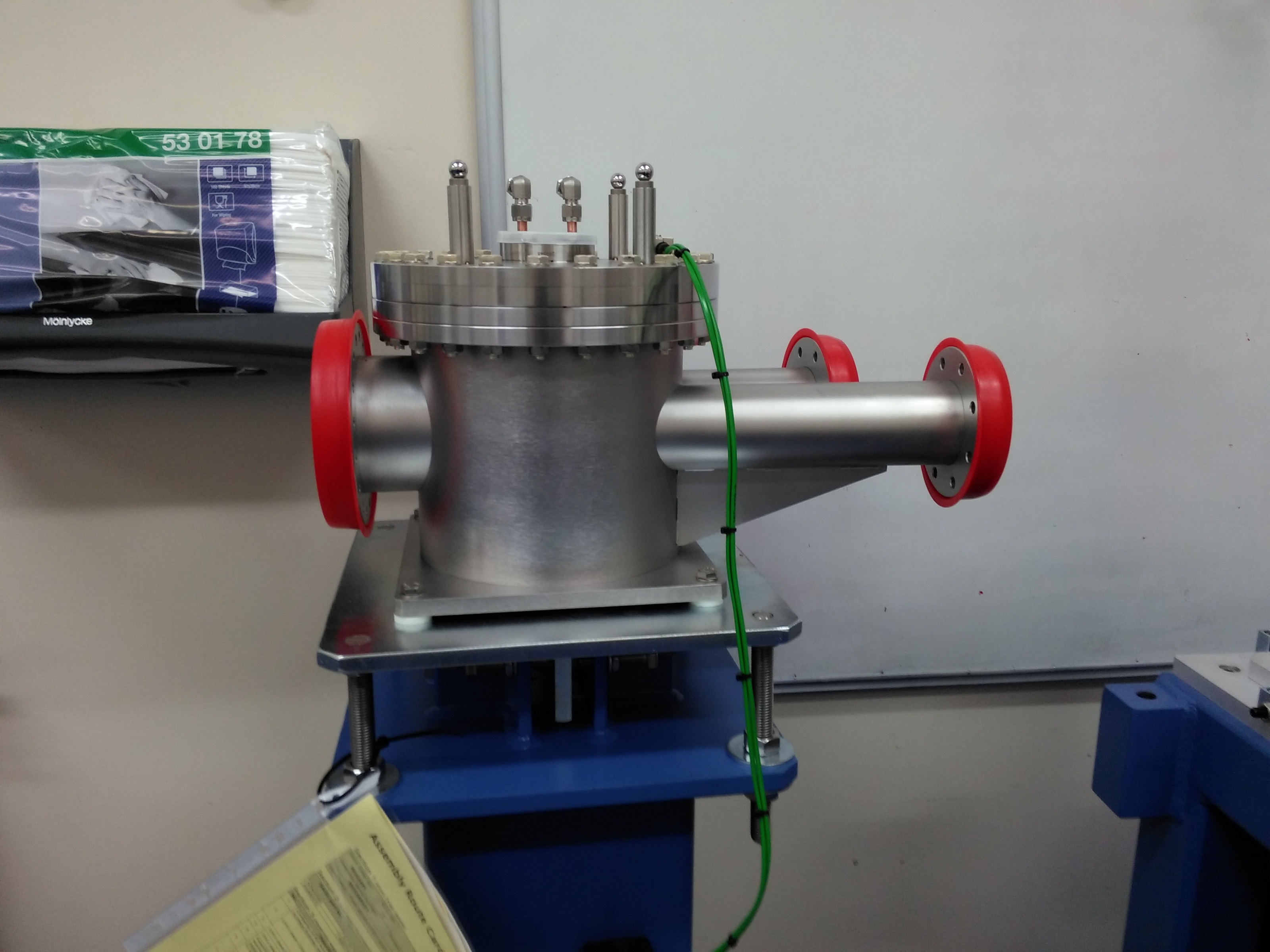
Ends of the transport pipe
These two shots show the ends of the transport pipe. Each end will be attached via bellows to the adjacent component.
| Fluorescent screen, installed in end station | Shutter in FOE |
 |
 |
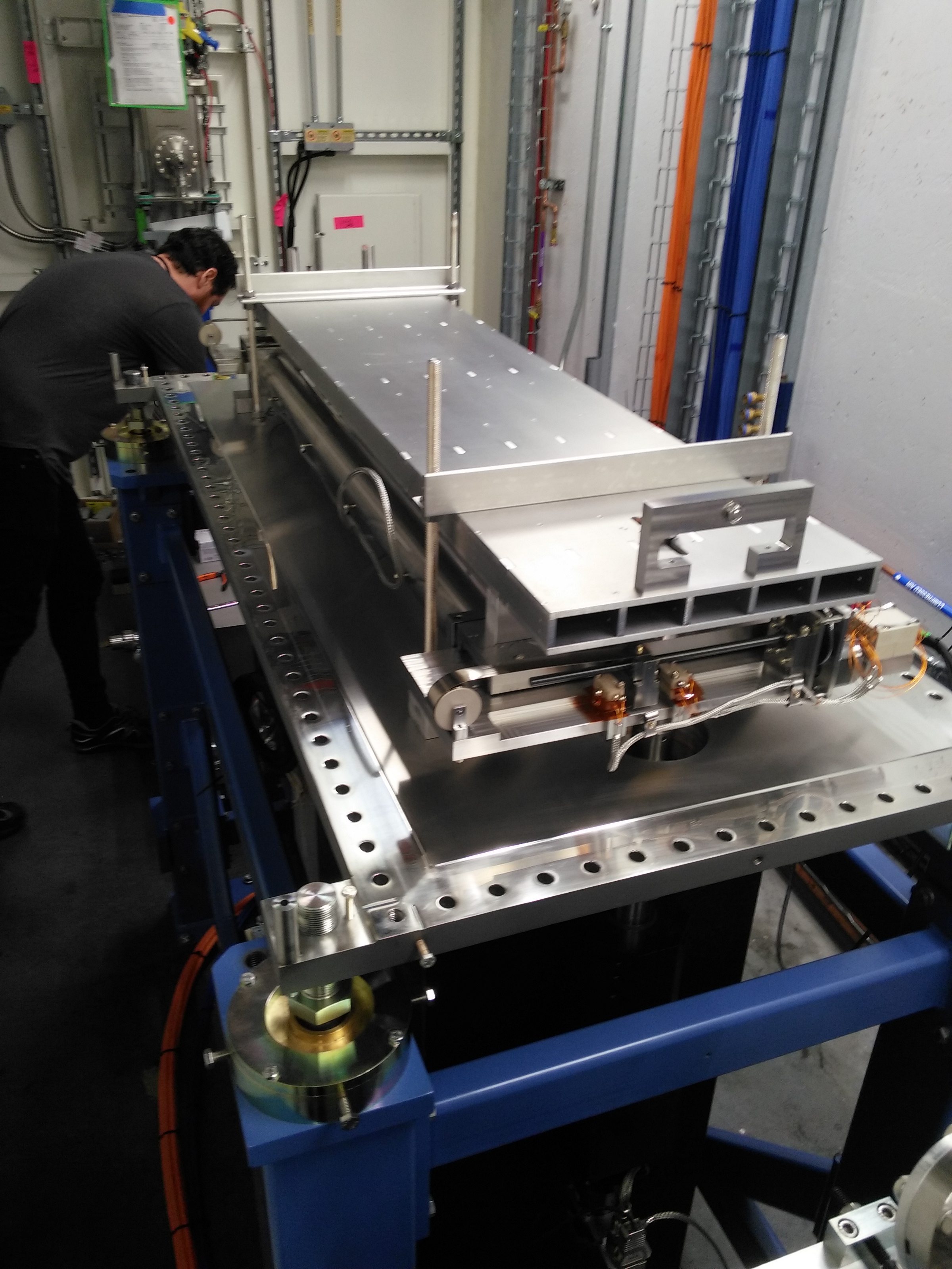
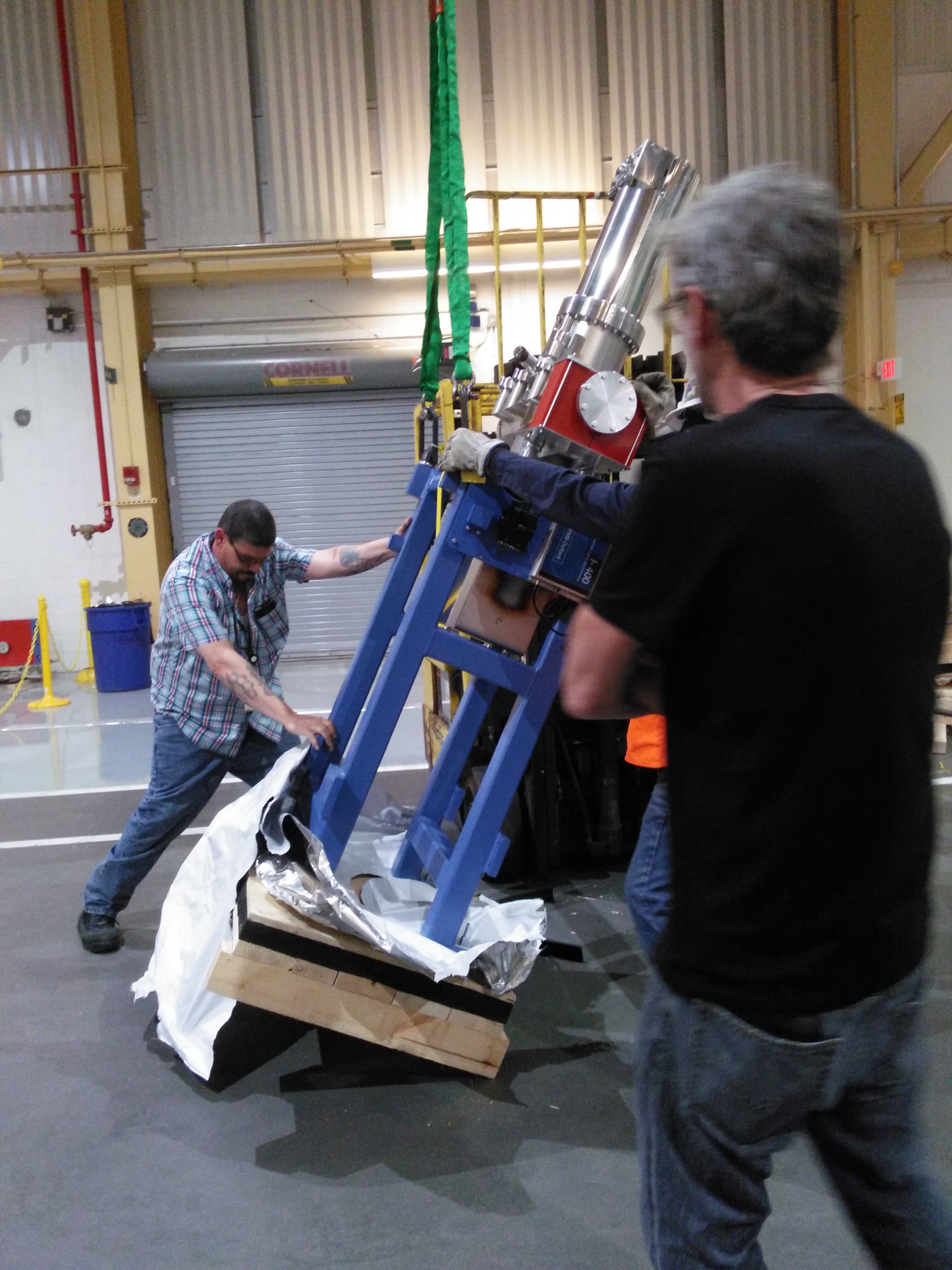
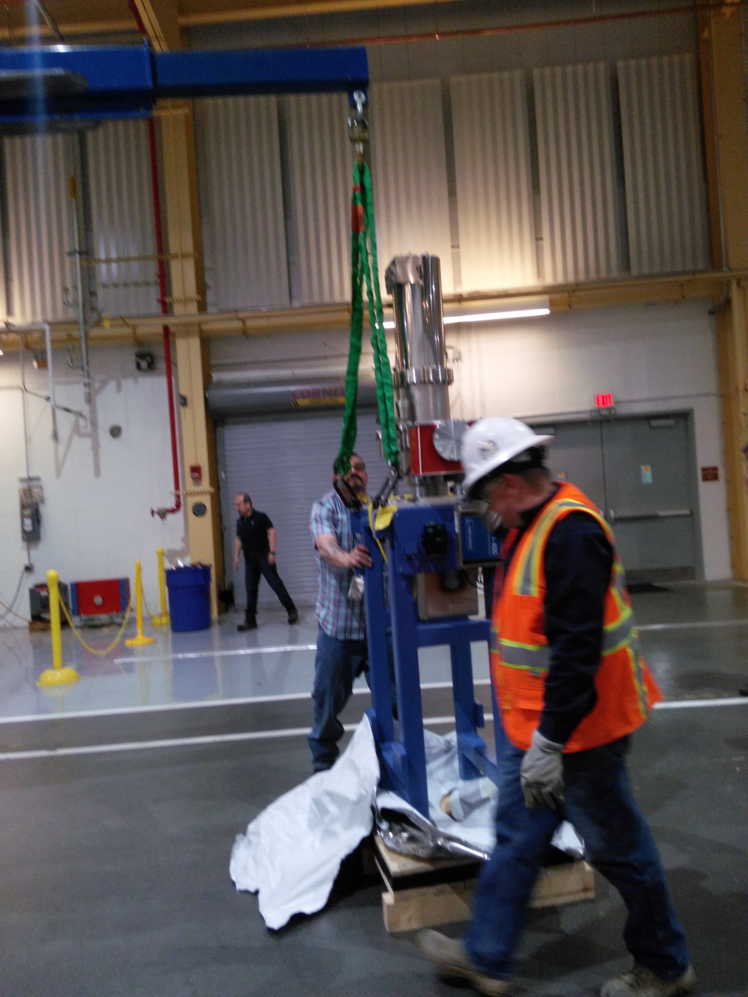
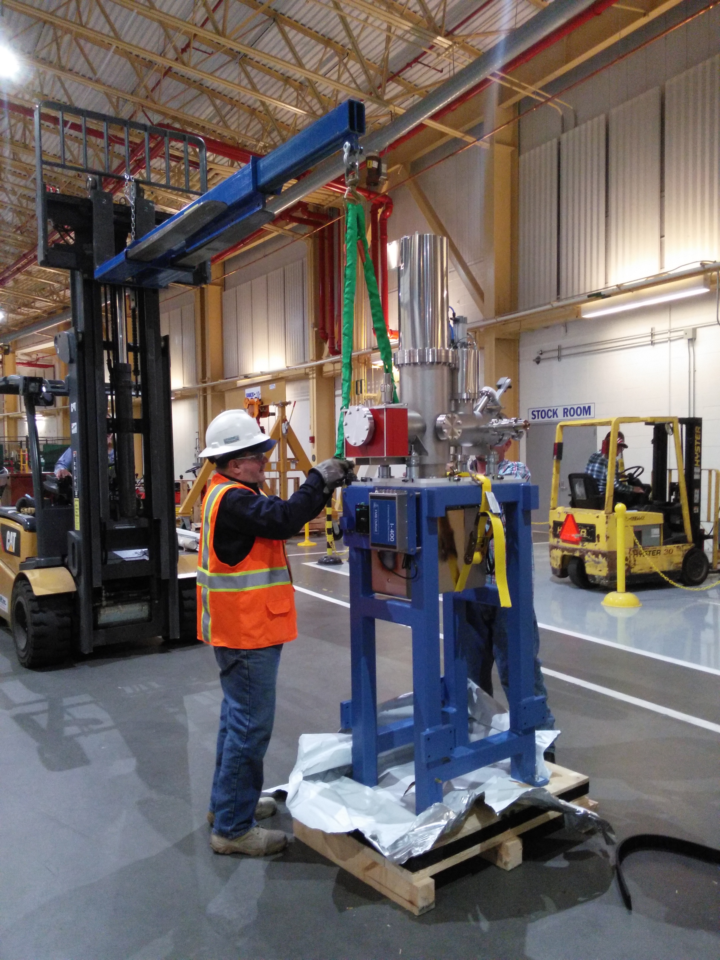
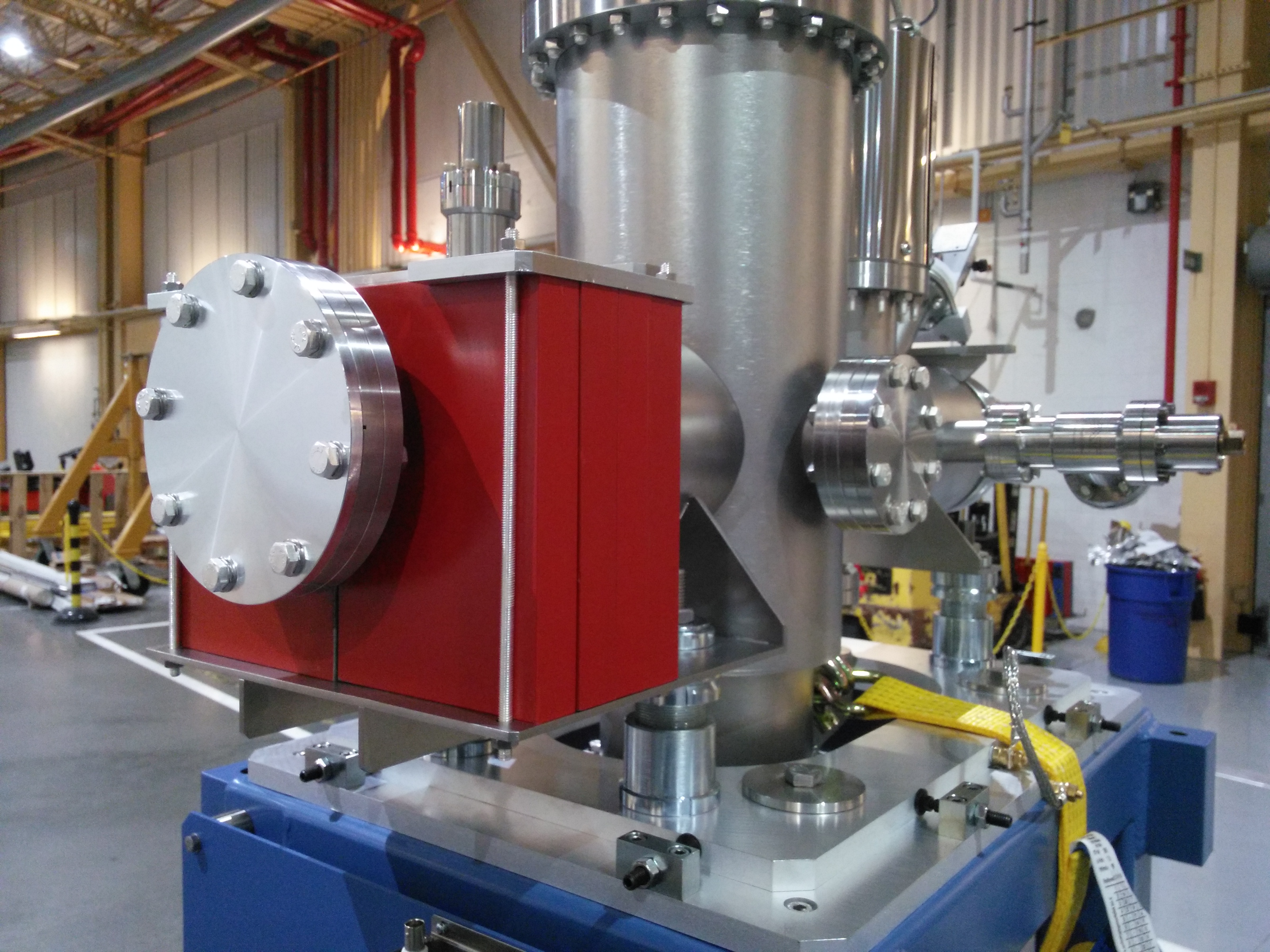
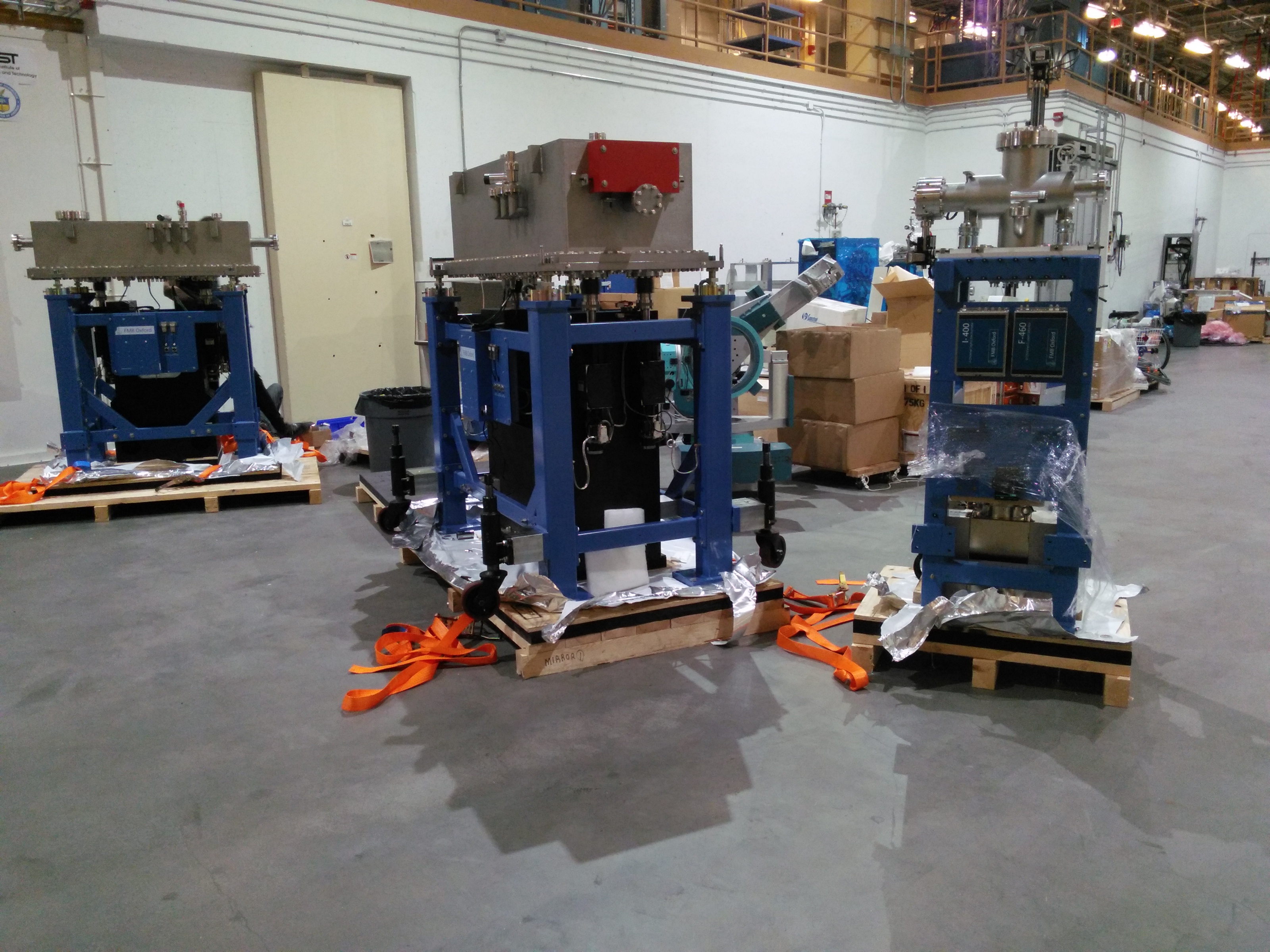
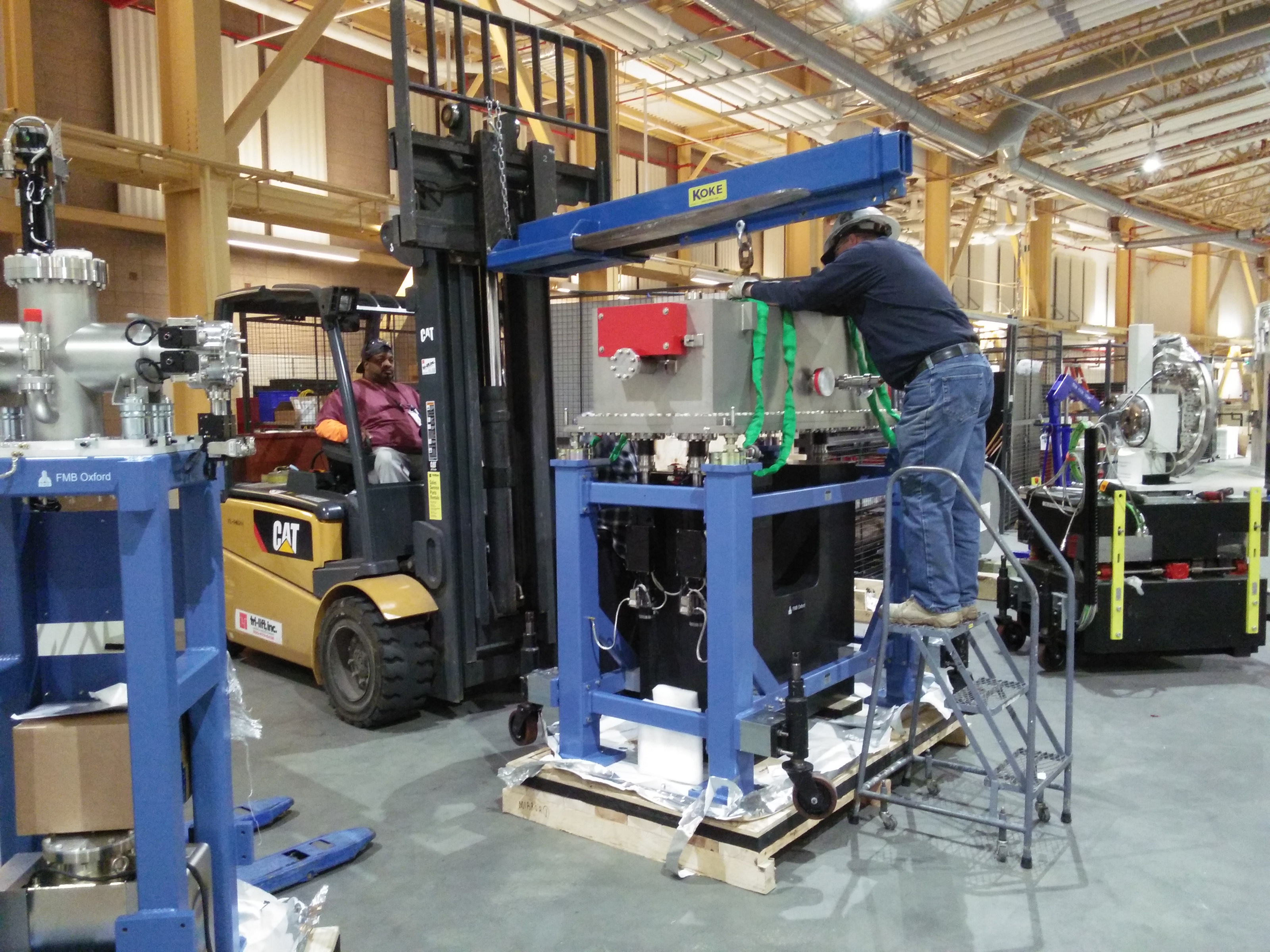
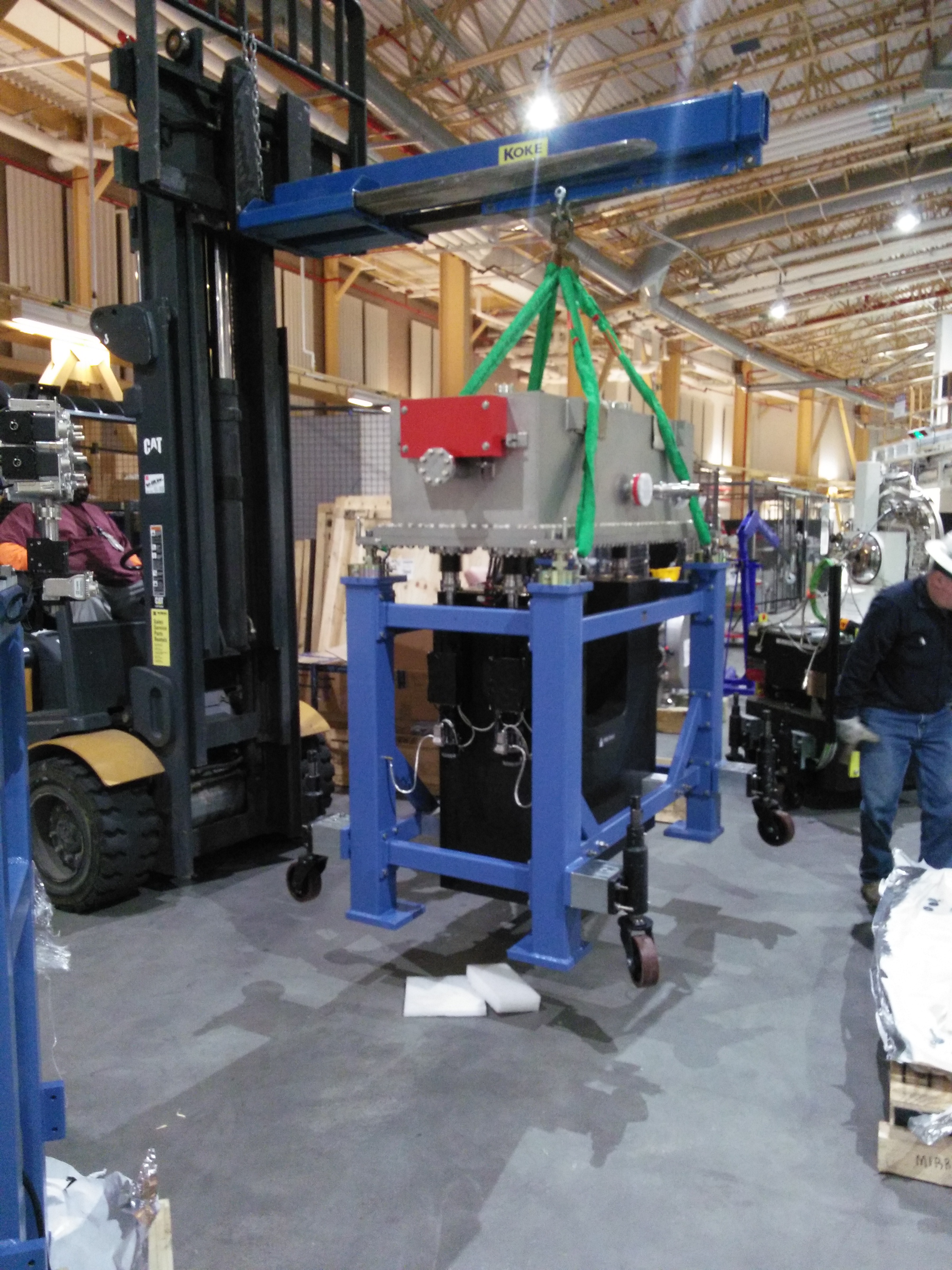
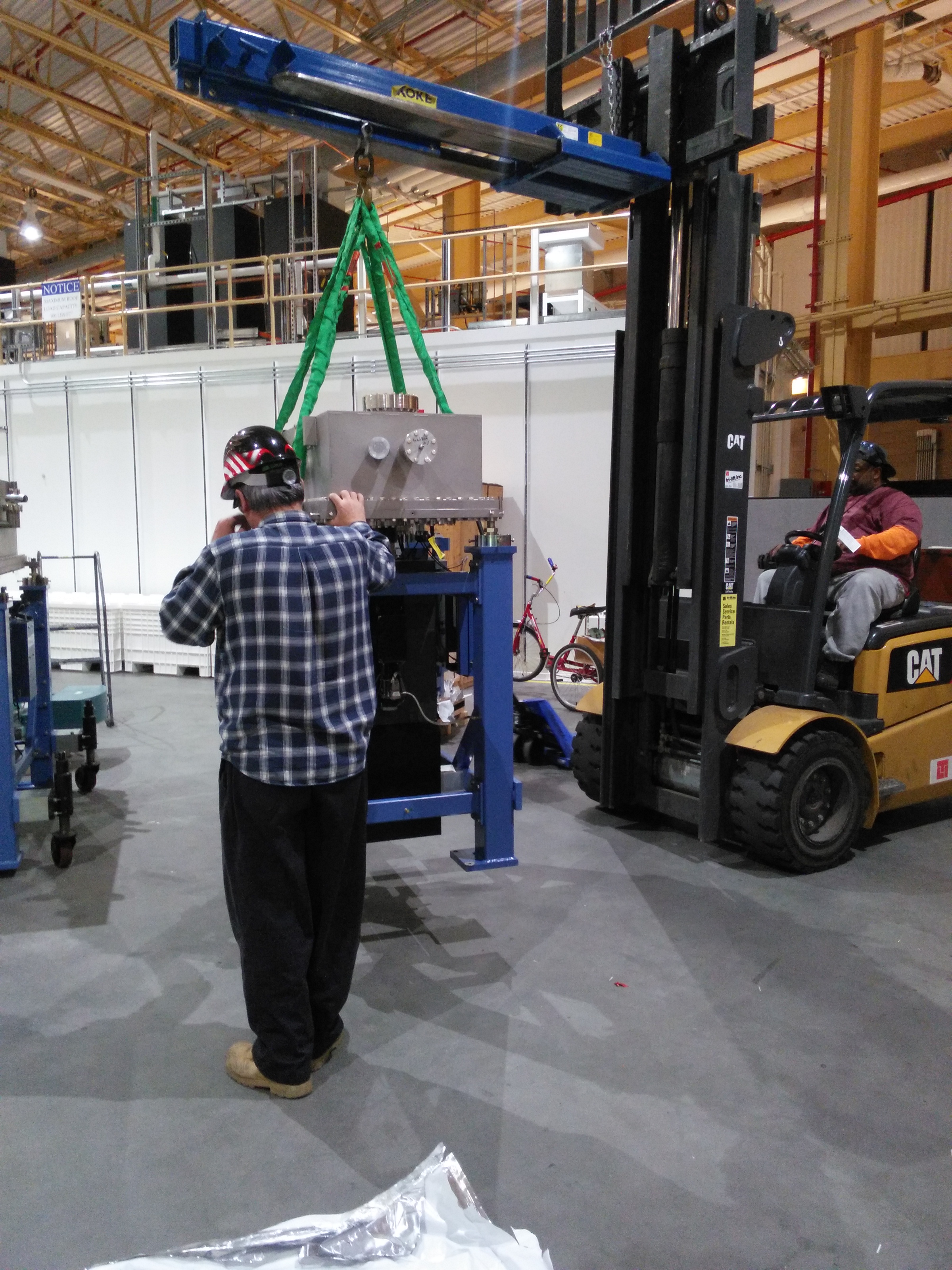
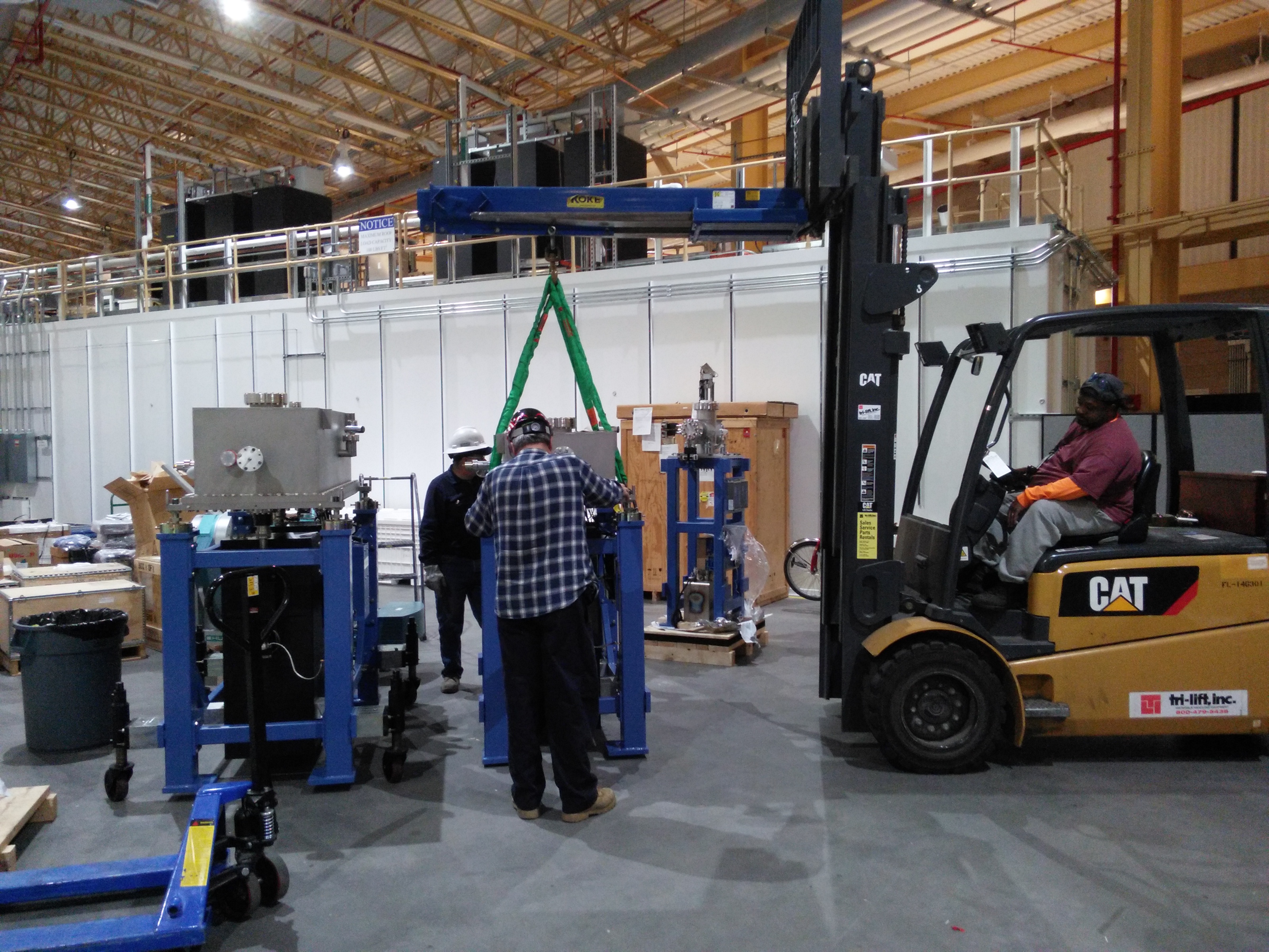
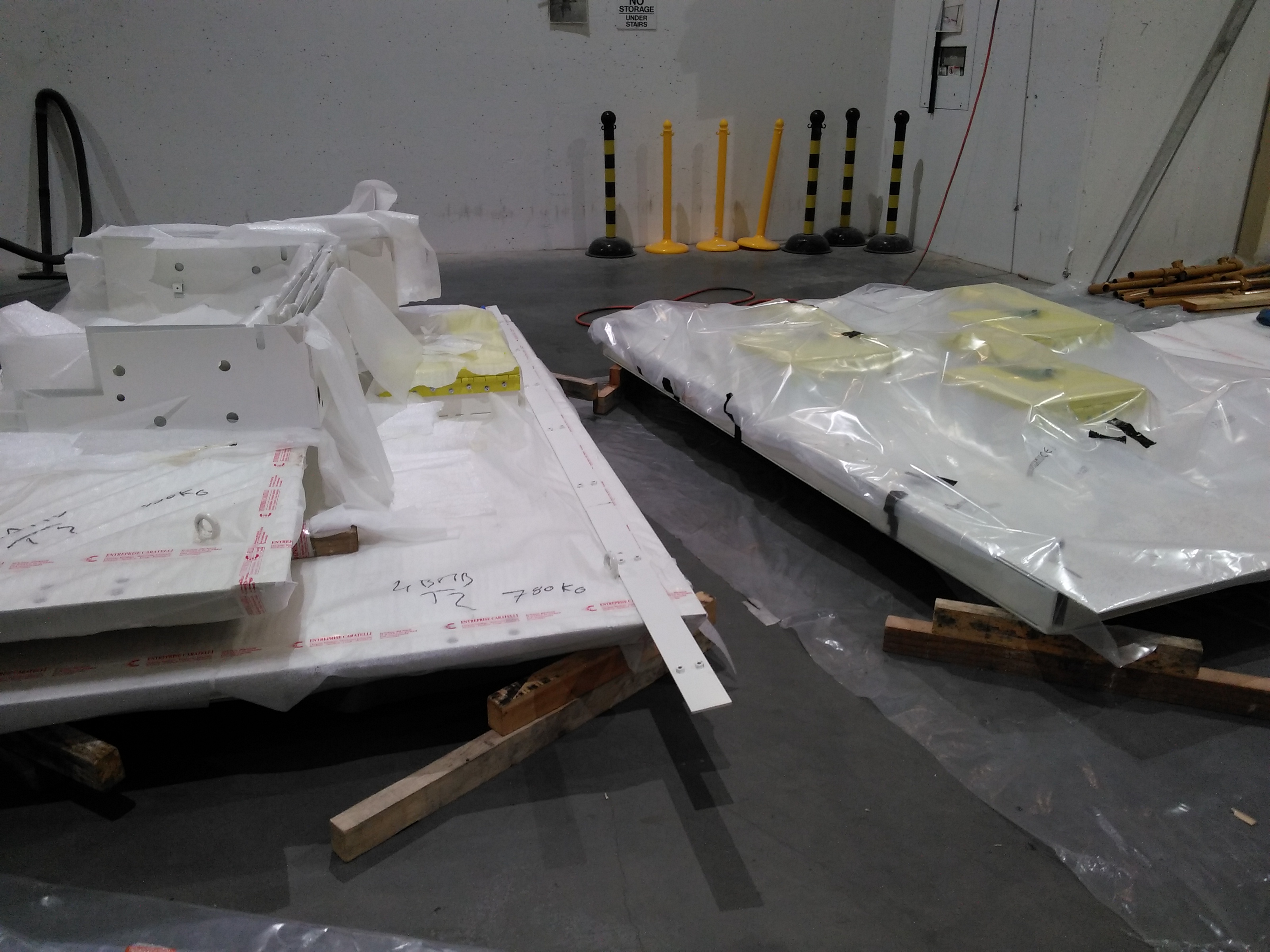
Removing M2, M3, and DM2 from their pallets
M2 is our toroidal focusing mirror. M3 is a planar harmonic rejection mirror. DM2 is the diagnostic module between the mono and M2, it has a screen and slits.
| M2, M3, DM2 as delivered | Preparing to lift M2 | M2 hoisted | M3 hoisted | Lining them up | Lifting DM2 |
 |
 |
 |
 |
 |
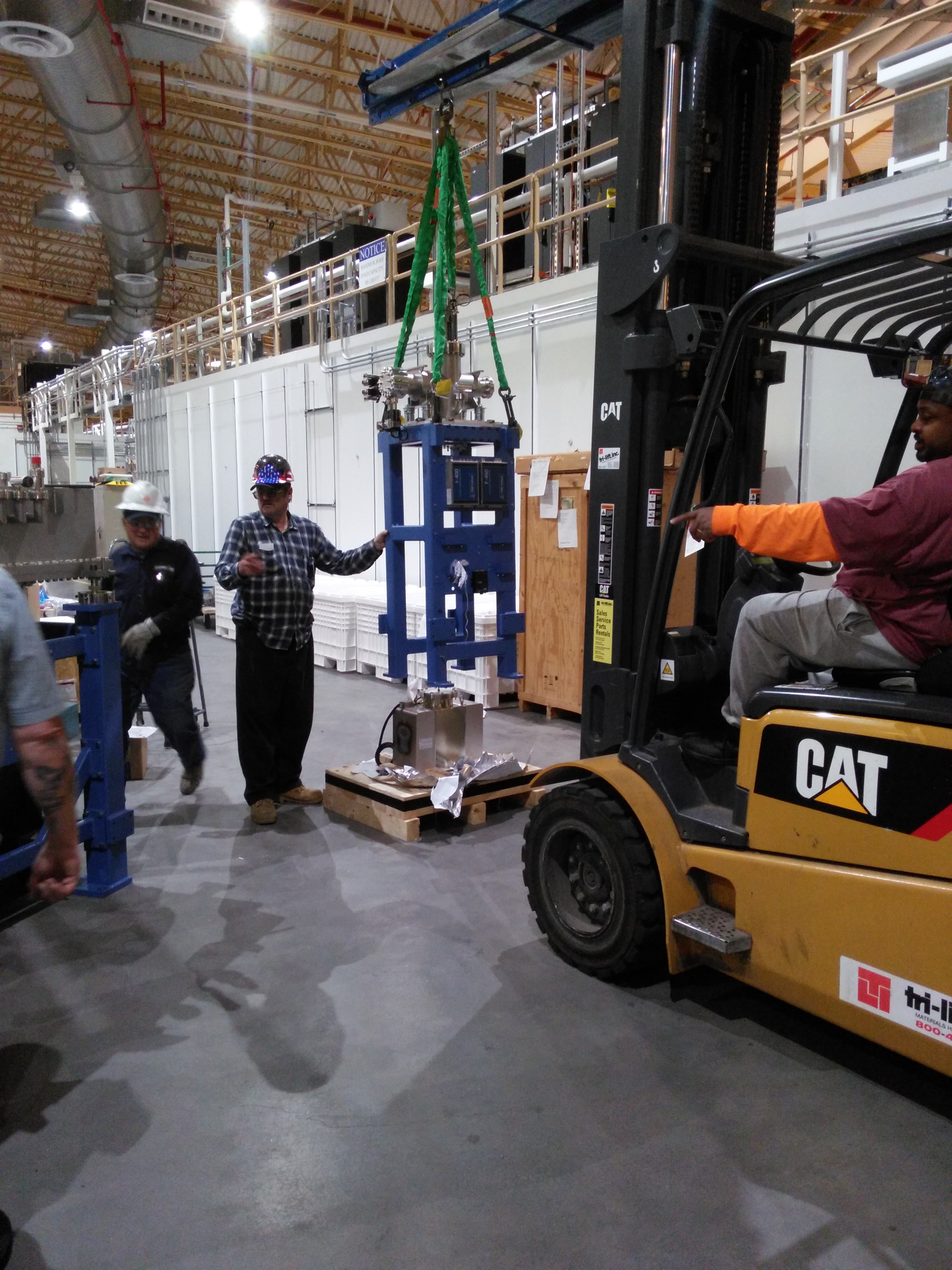 |
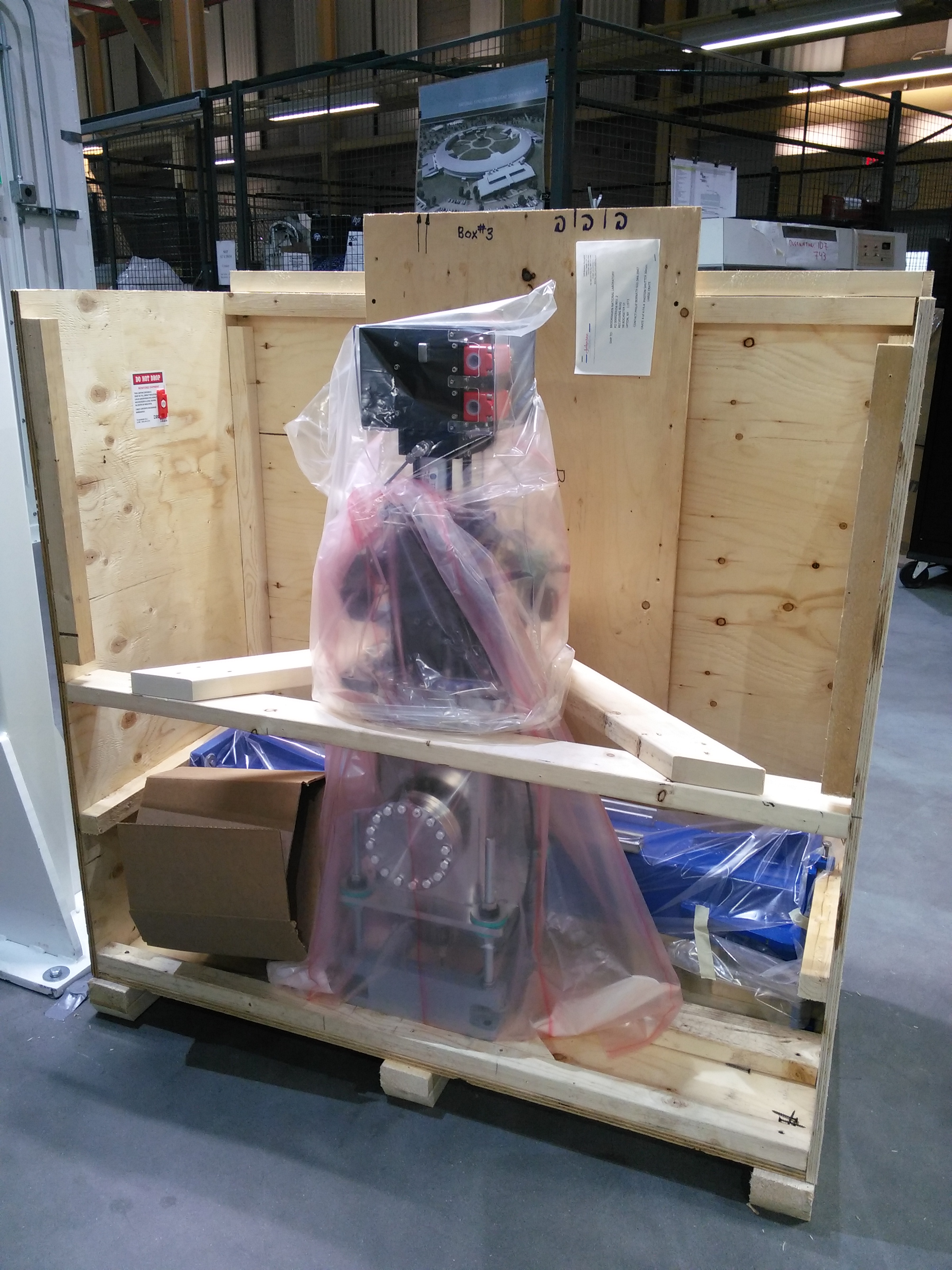
Figure 3: Mono, M2, M3, and DM2 all staged and ready to go.
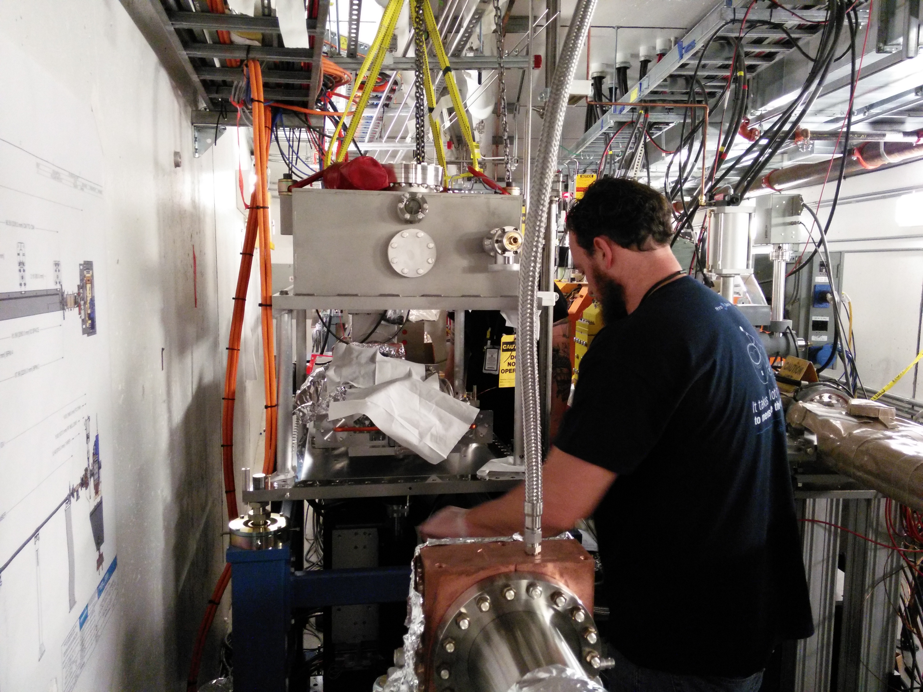
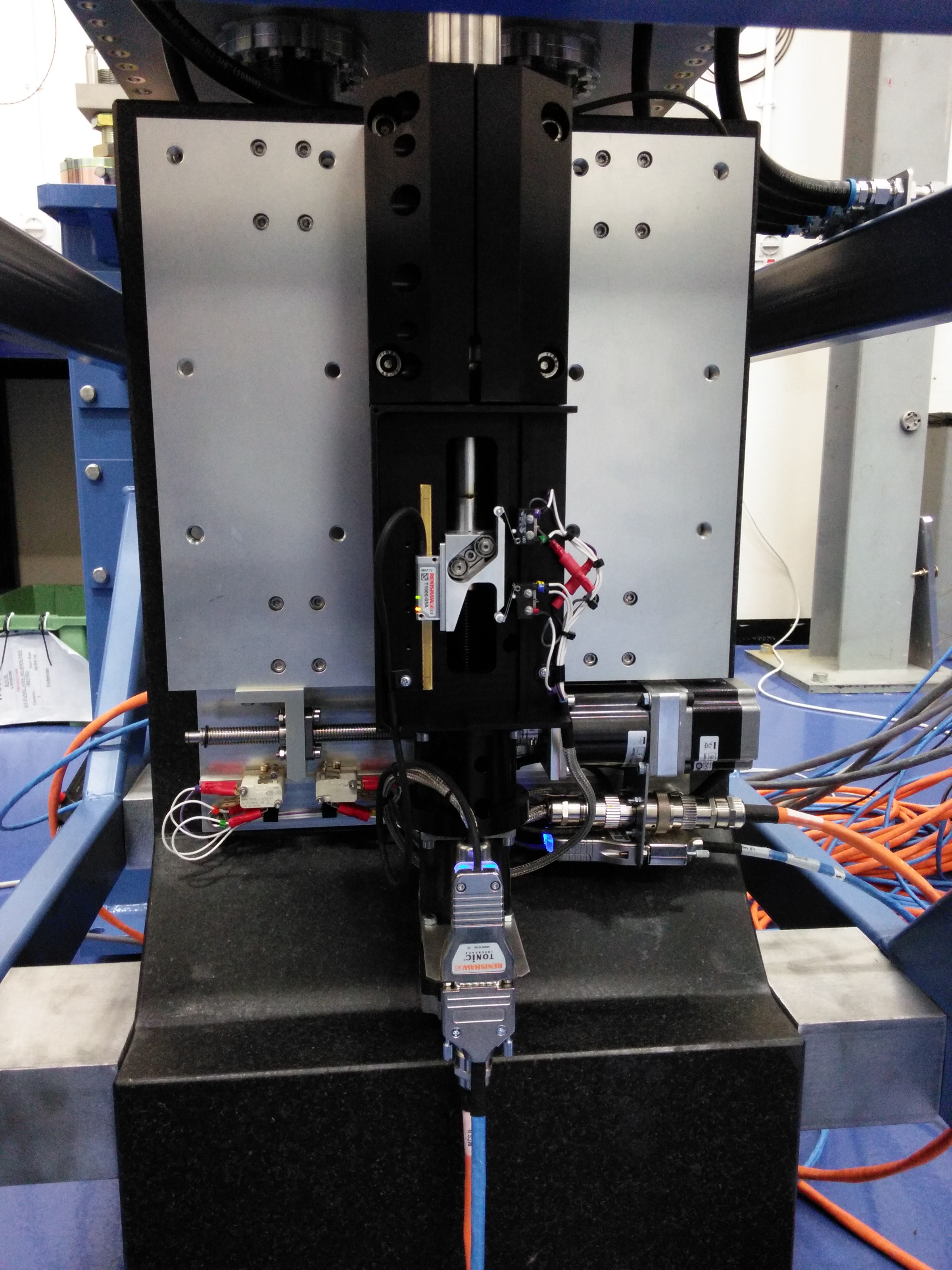
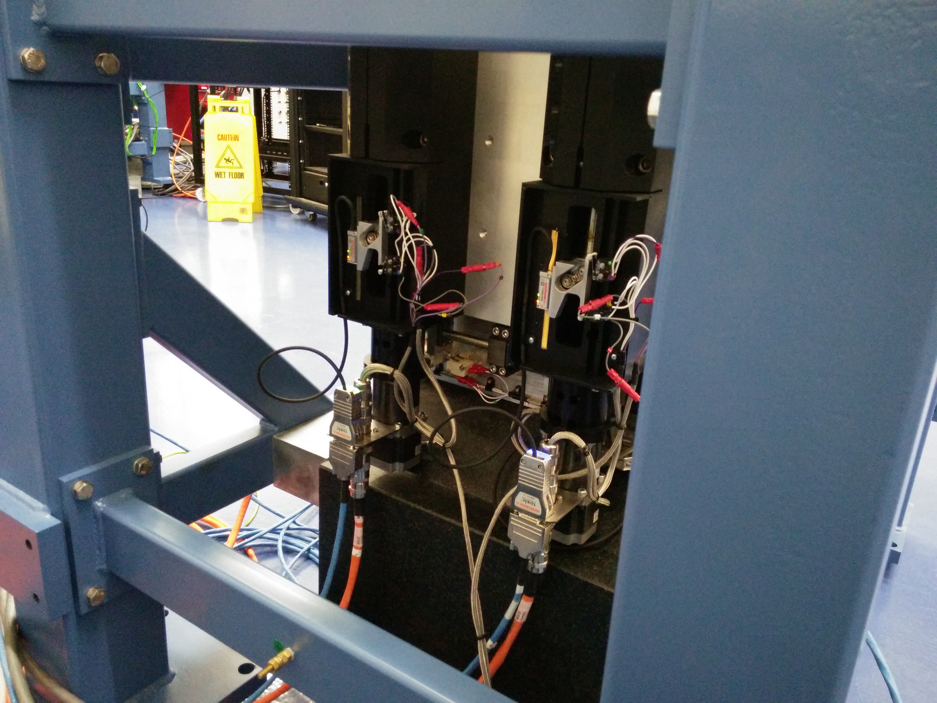
May 9, 2017
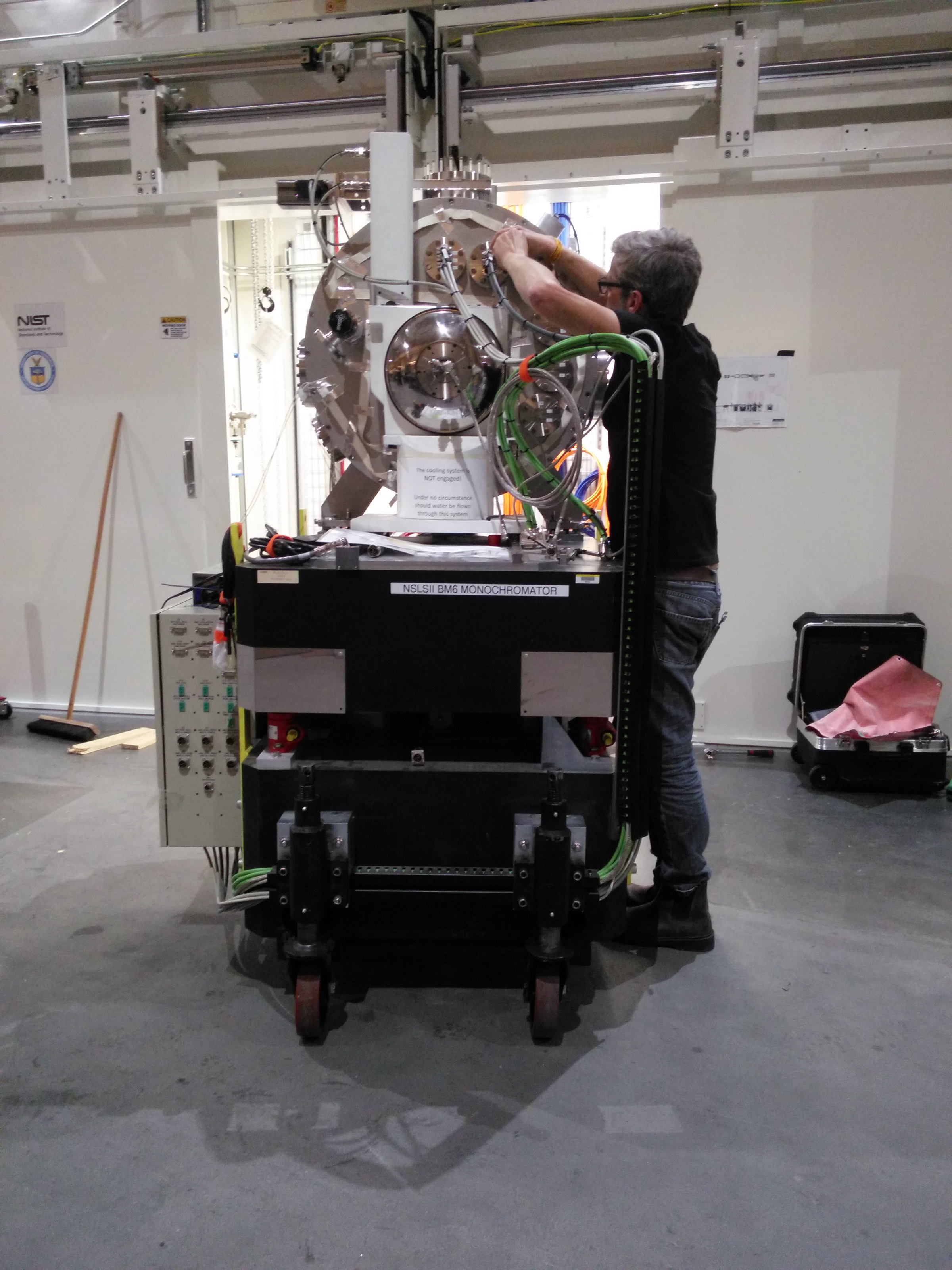
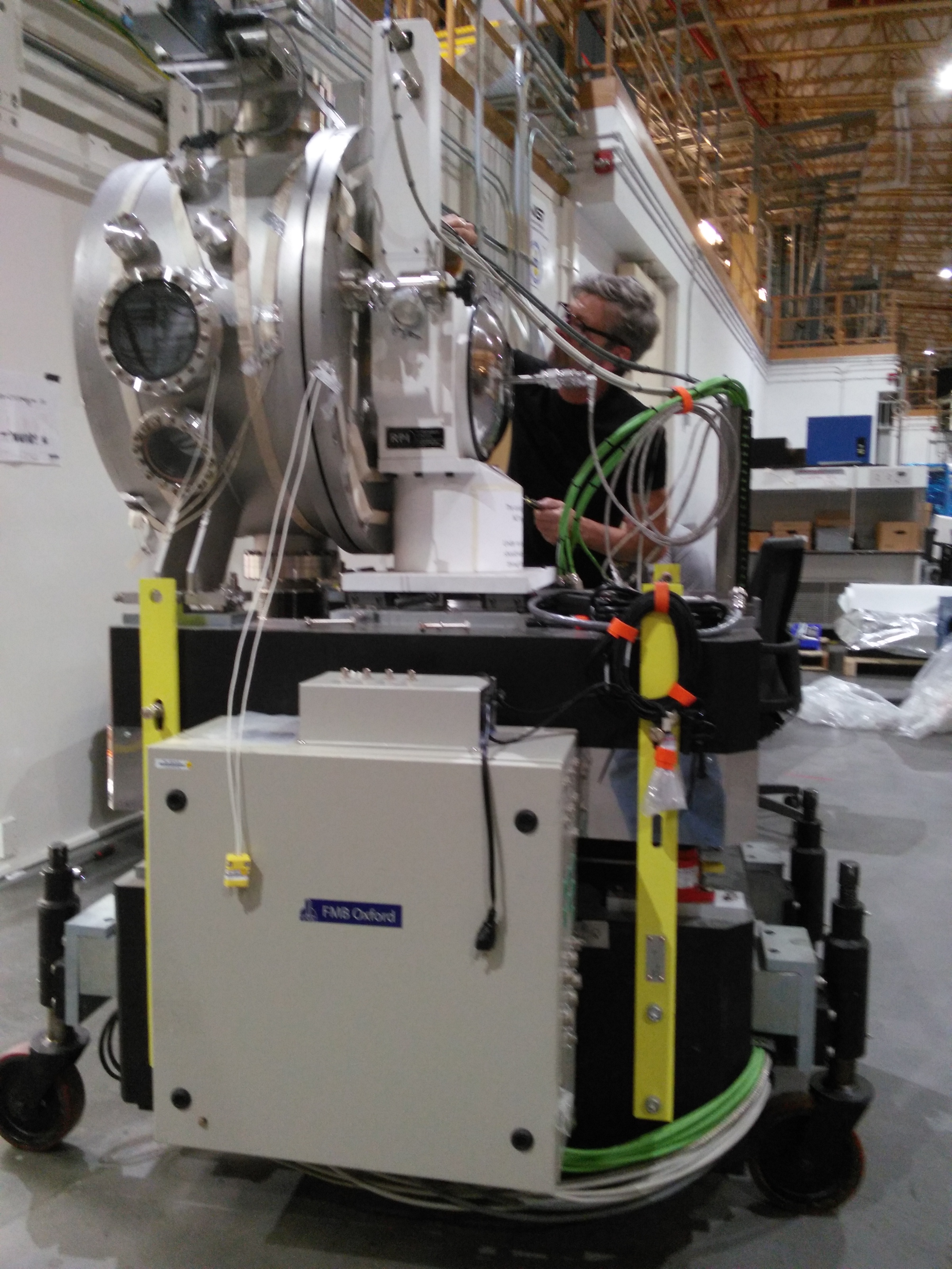
Monochromator
Ian begins work to replace the crystal cage. The mono has been removed from the hutch to allow space to install the first diagnostic module, which will arrive in a few days.
| Beginning work | Disassembling |
 |
 |
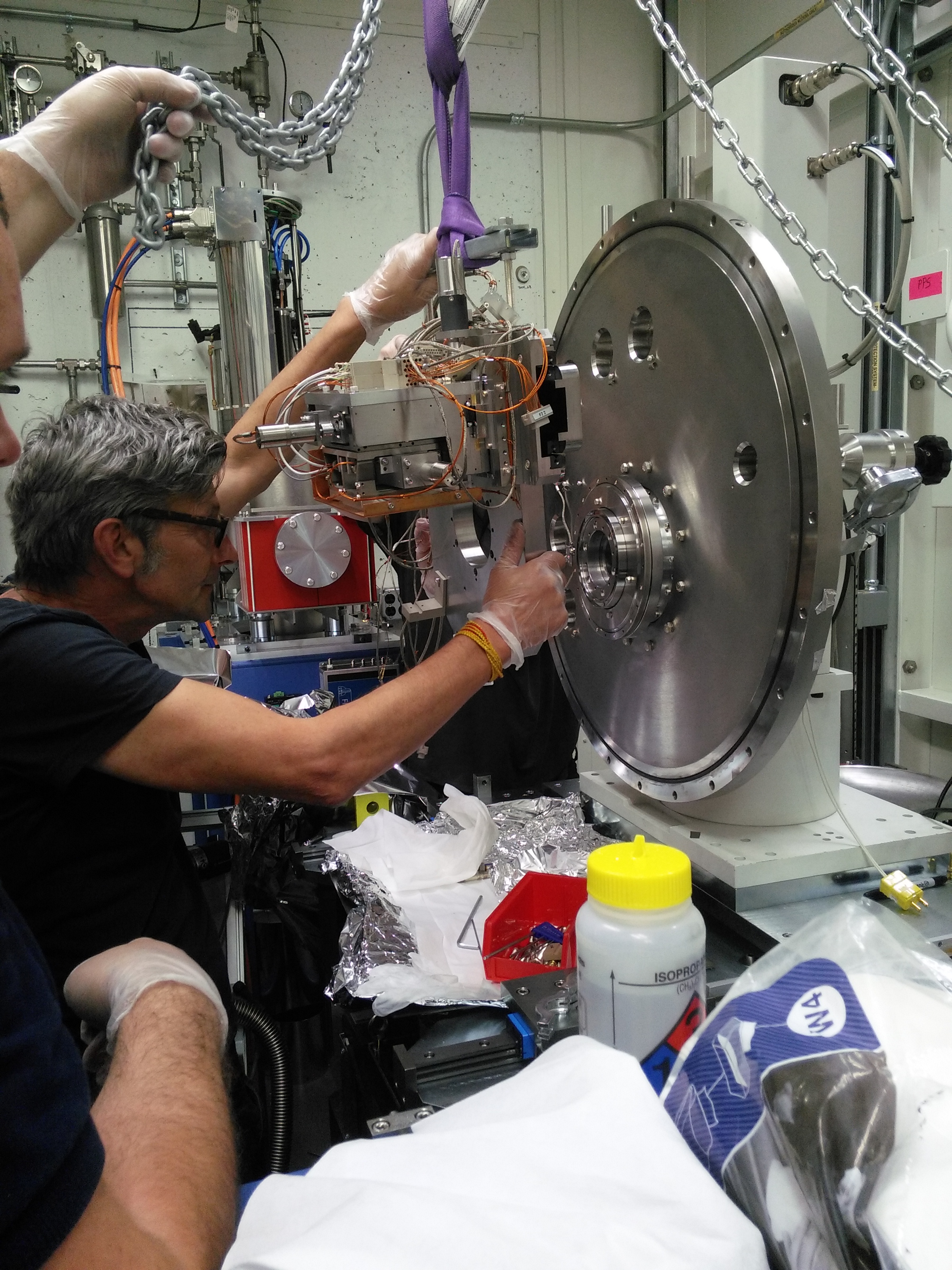
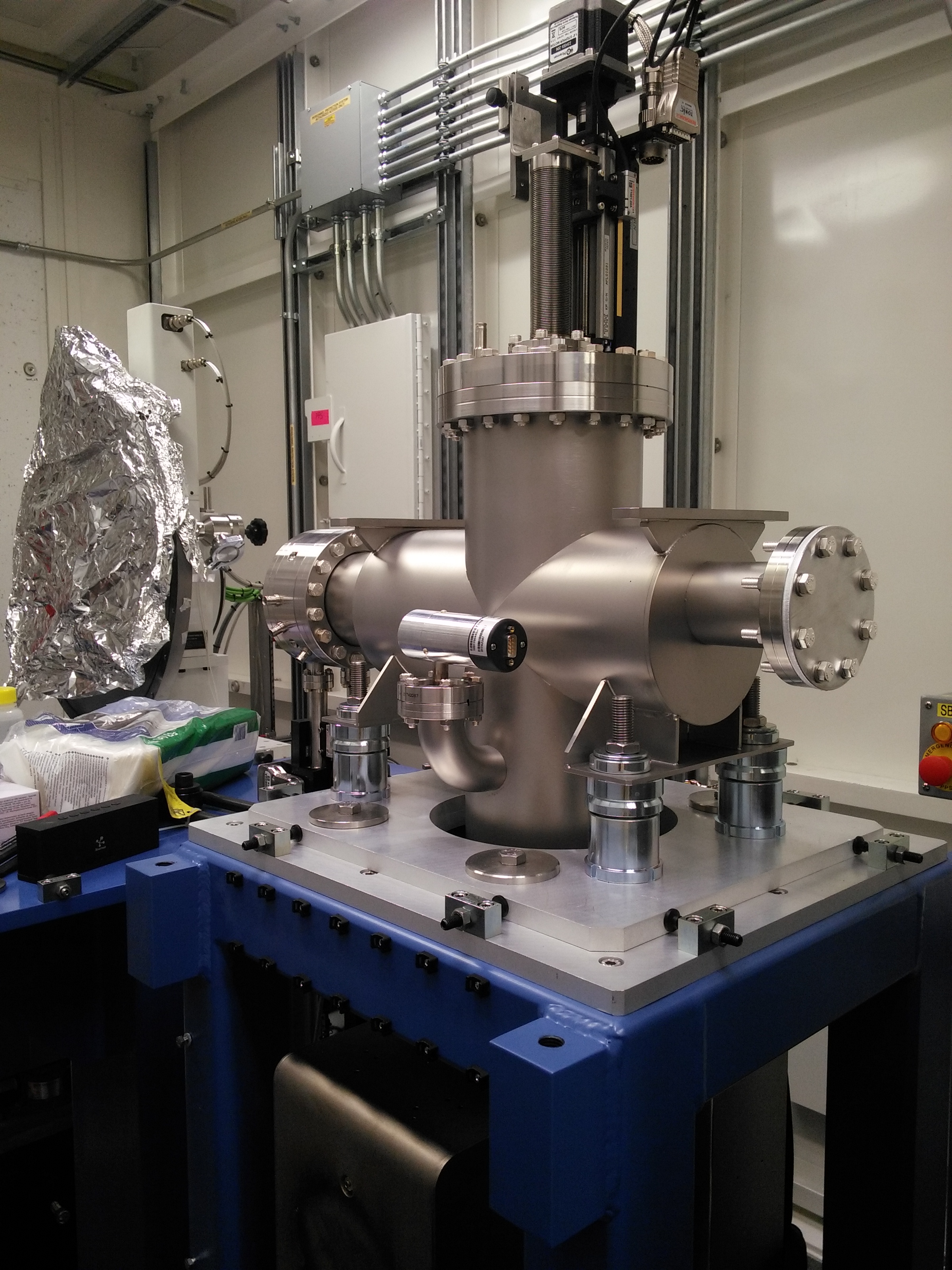
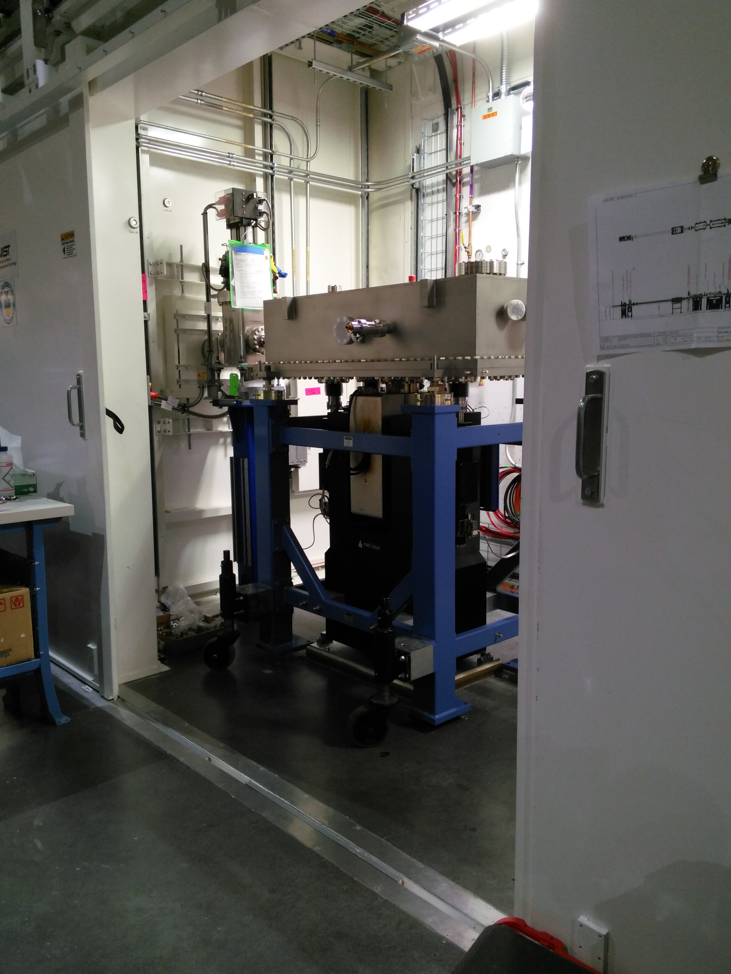
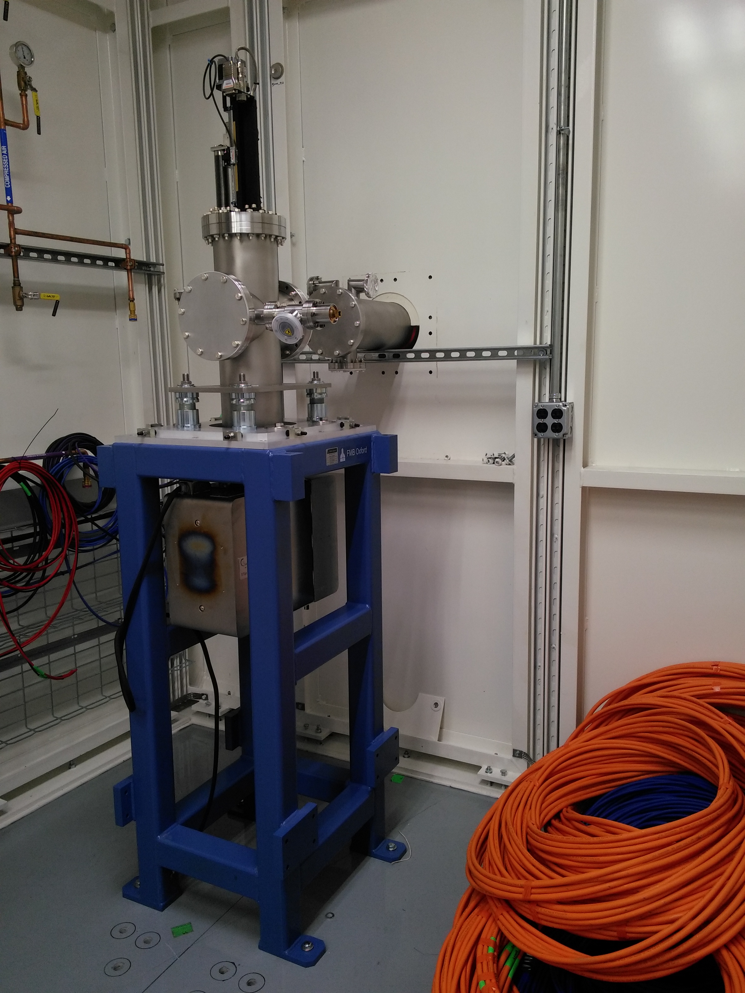
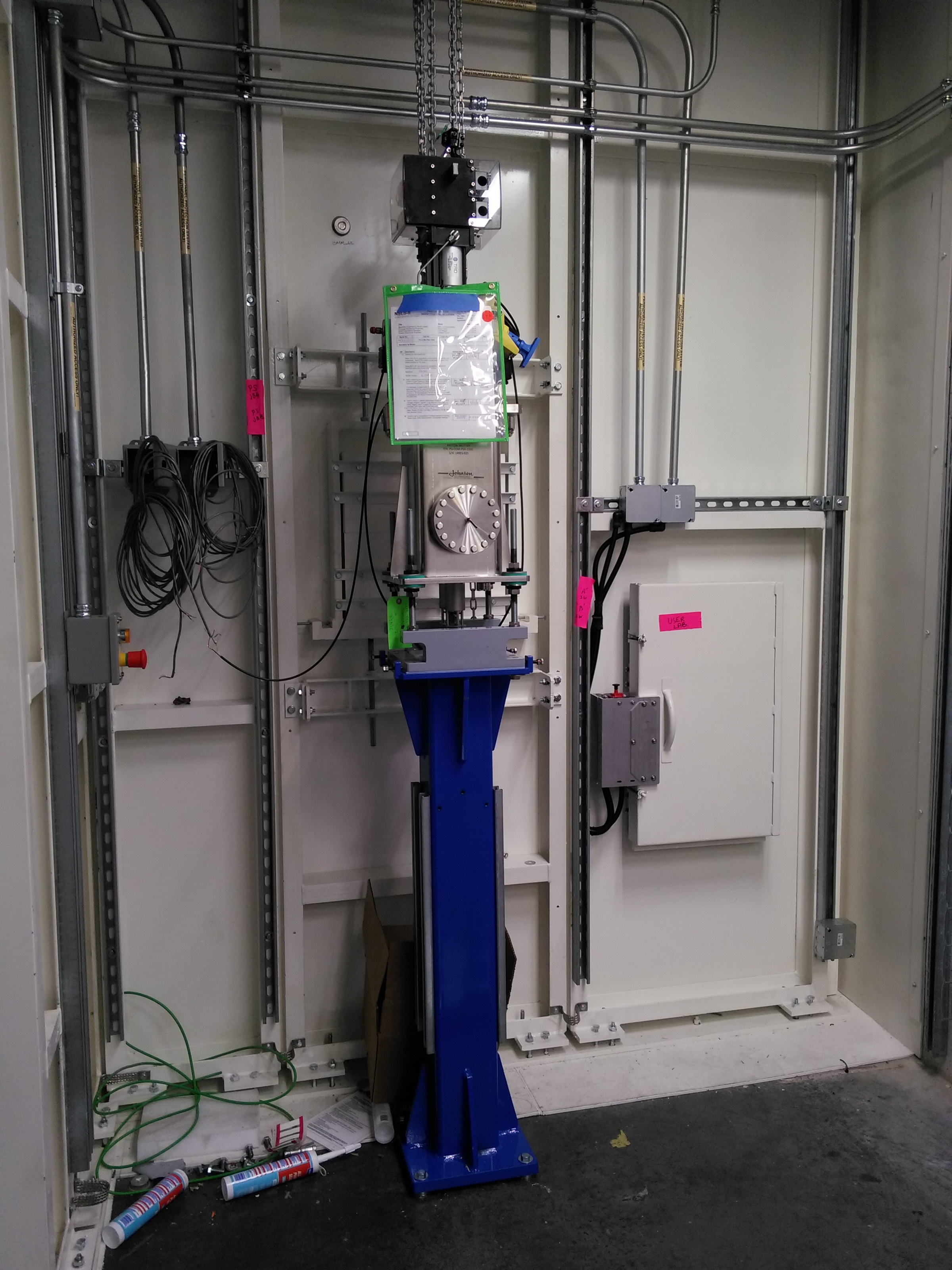
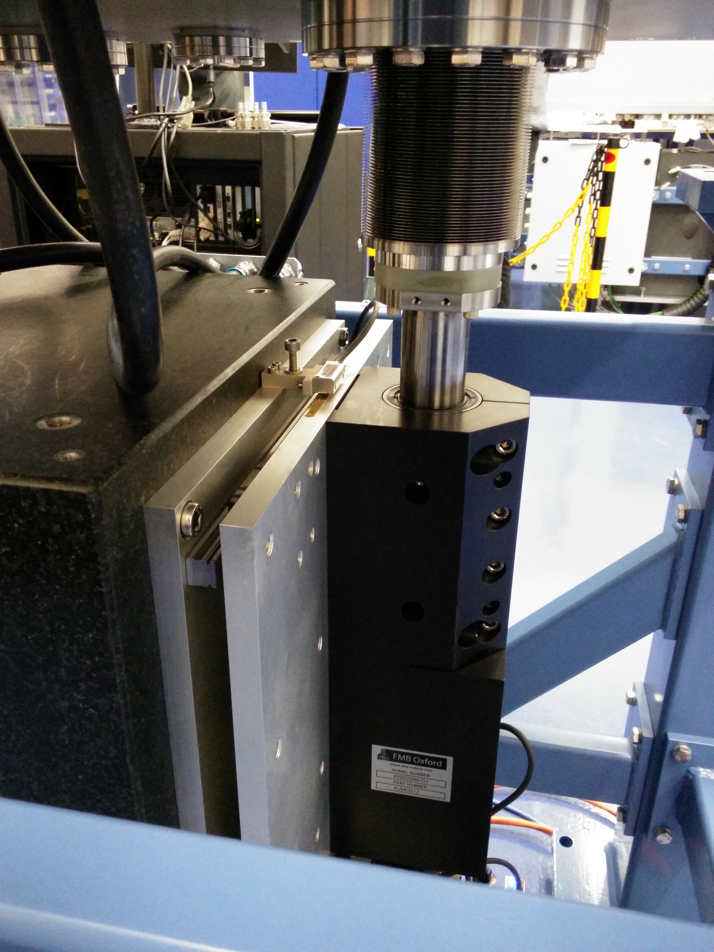
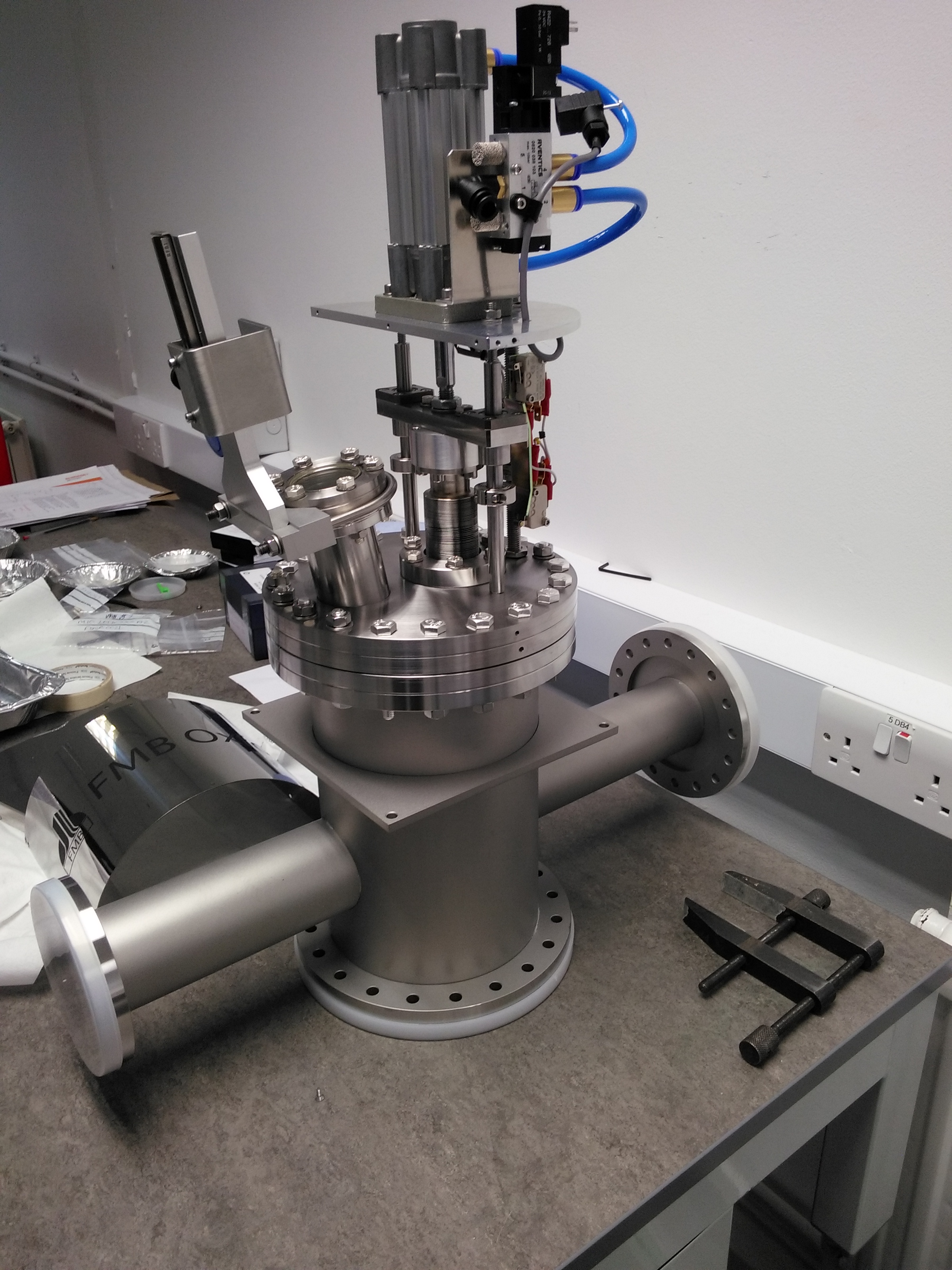
Uncooled fluorescent screen stand
Figure 4: Beau is working on attaching the ion pump to the vacuum vessel. This is the first item in the end station.
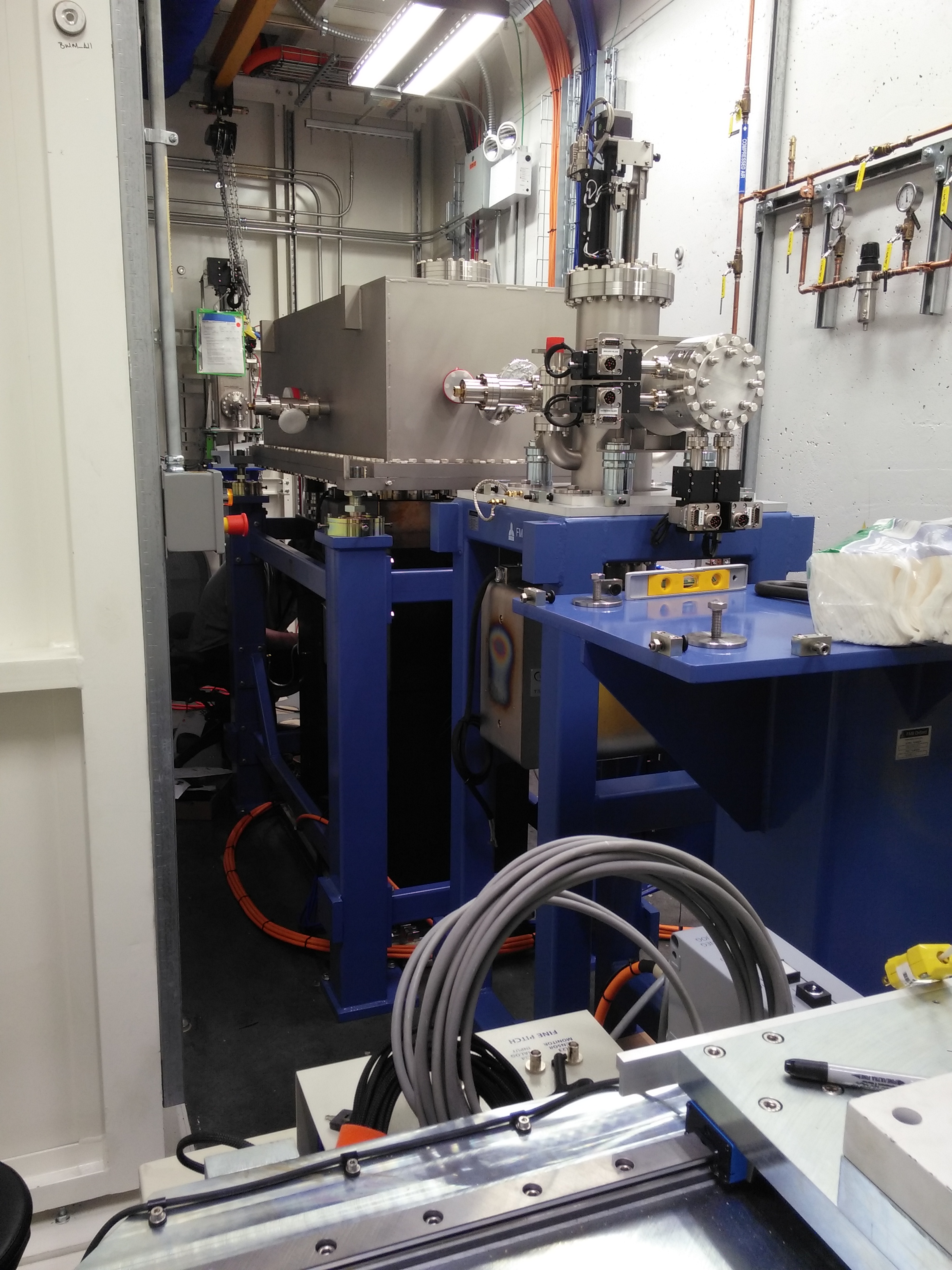
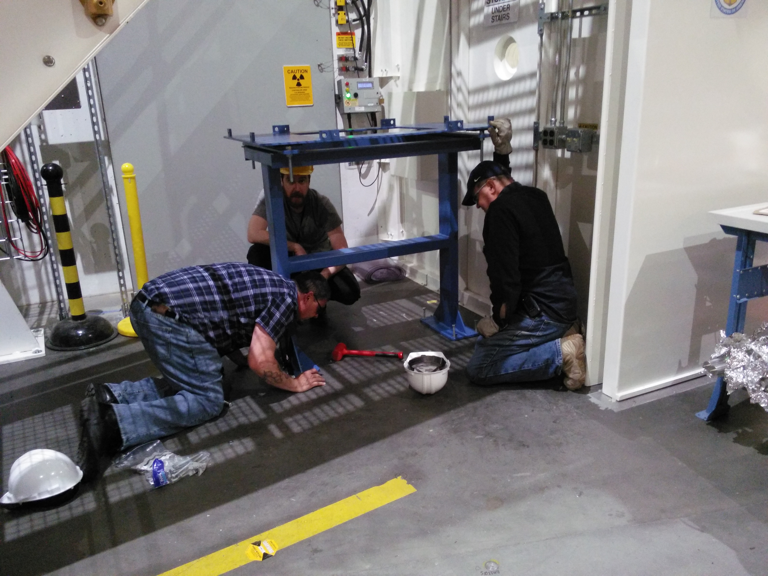
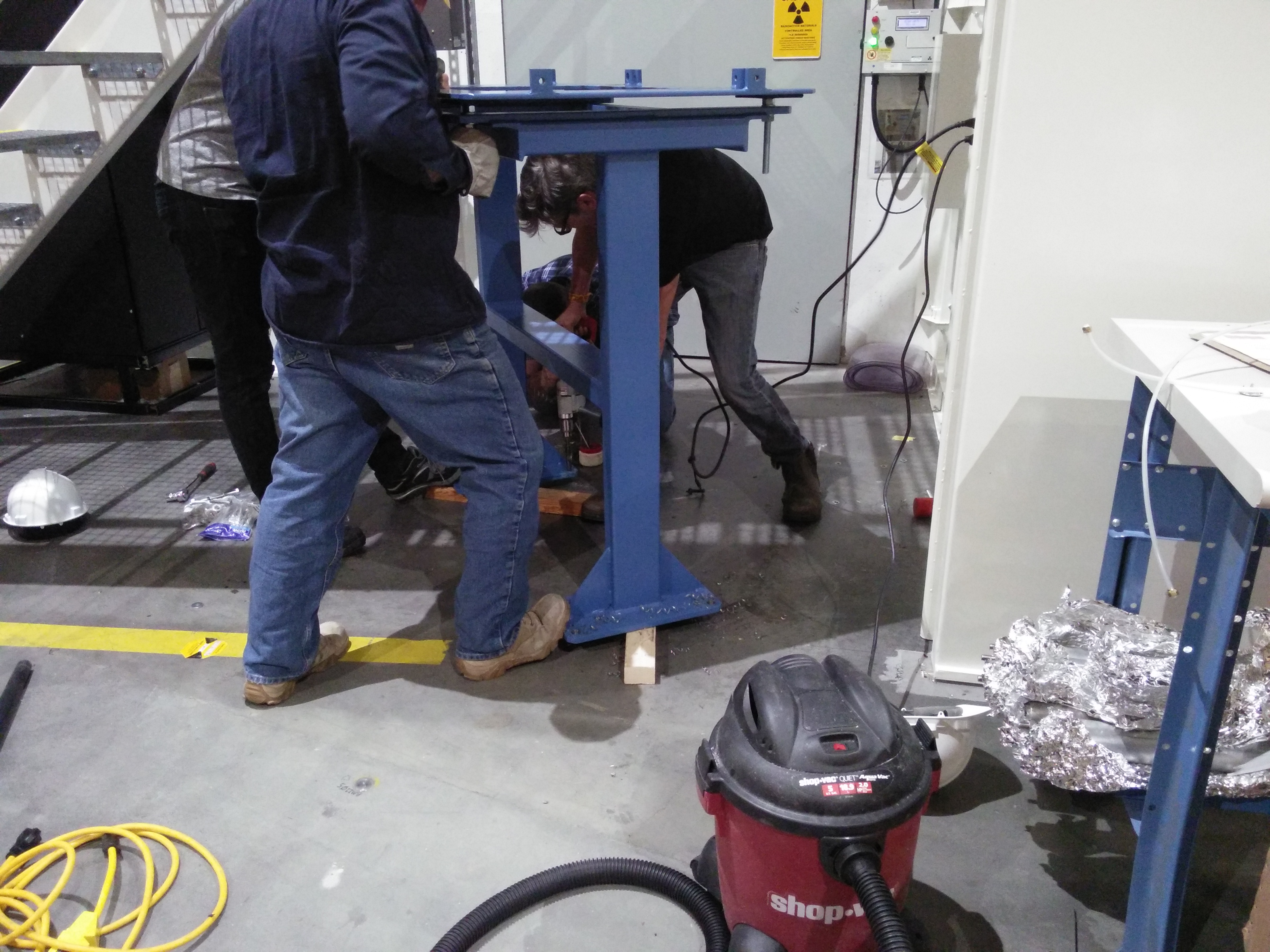
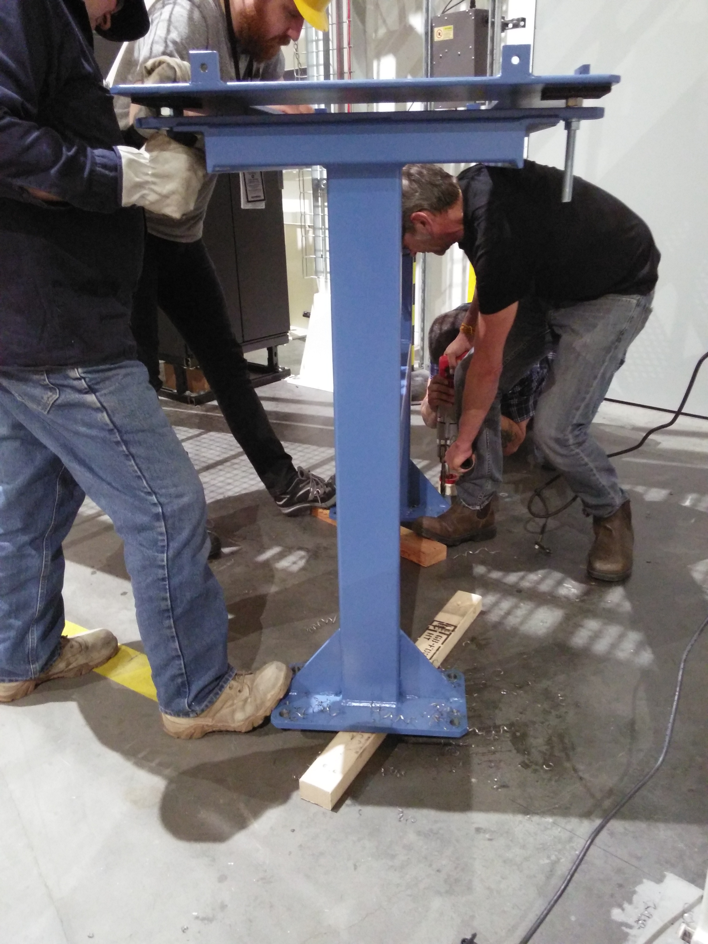
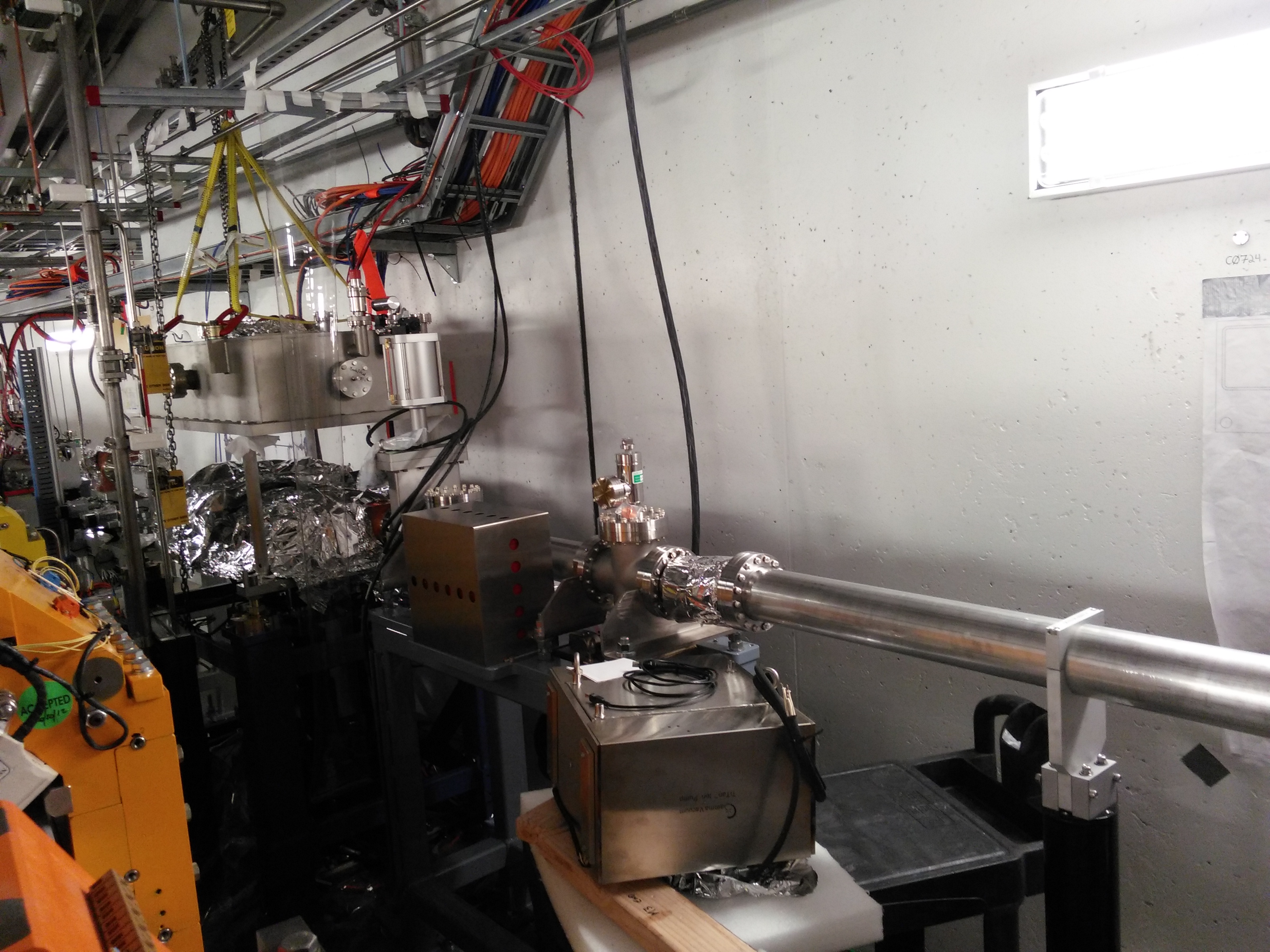
Pump stand for the transport pipe
This stand supports a shielded box which holds an in-line ion pump. This, along with the pump on the fluorescent screen shown above, pumps out the transport line between the hutches.
| The holes don't quite line up with the holes in the floor | Art the rigger is waiting to lift the shielded box | Ian drills out the holes on the stand's legs | More drilling |
 |
 |
 |
 |
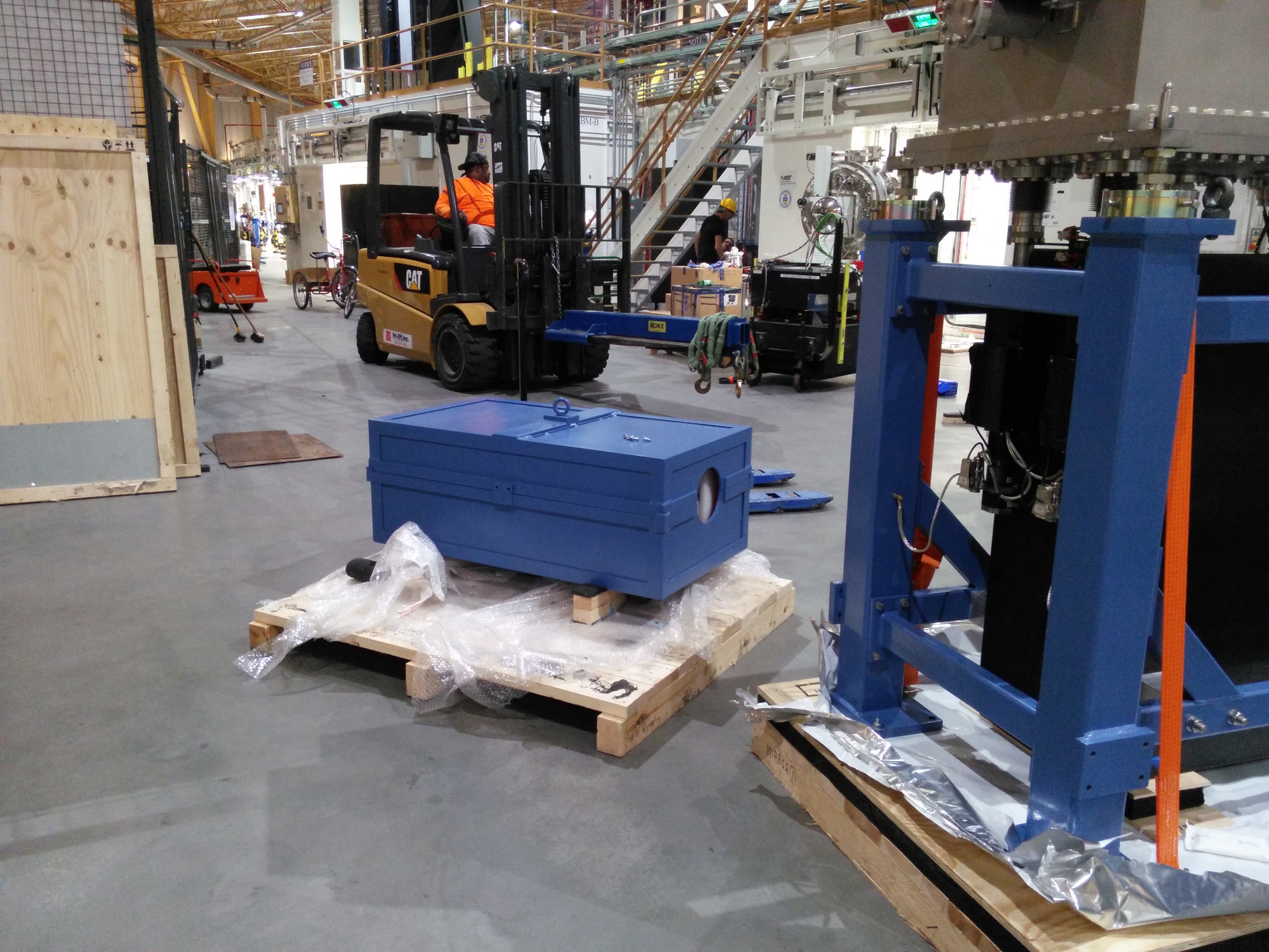
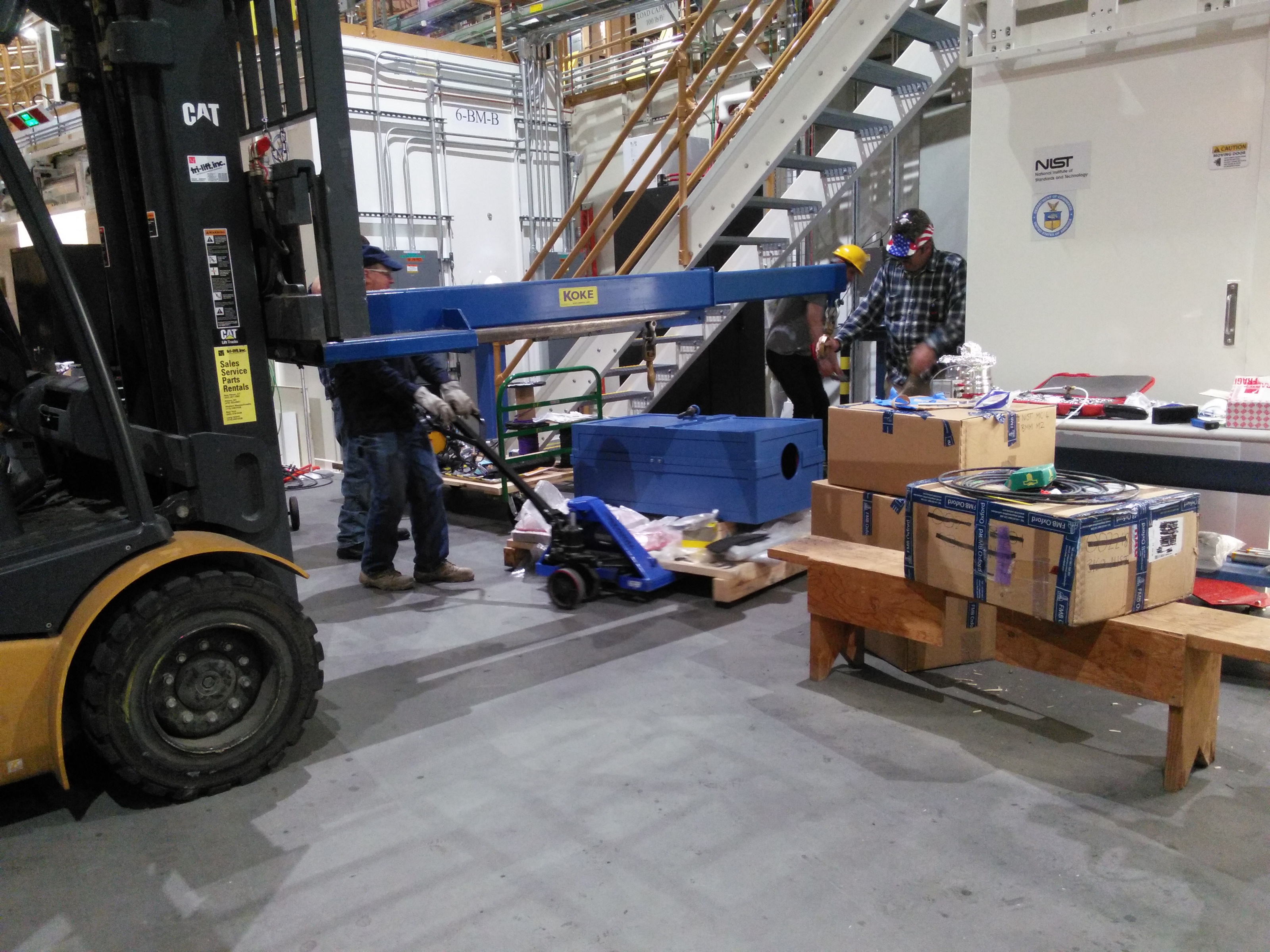
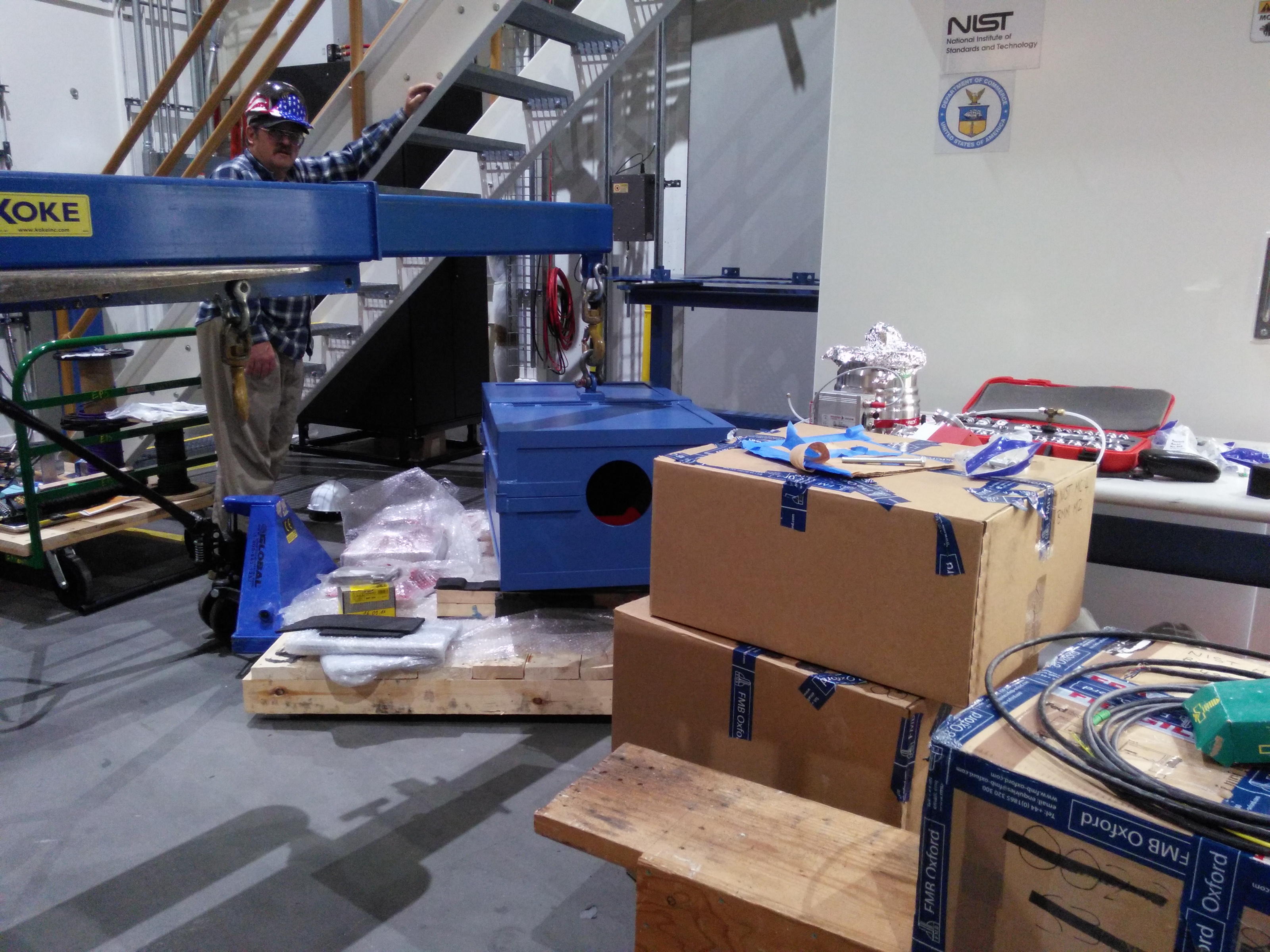
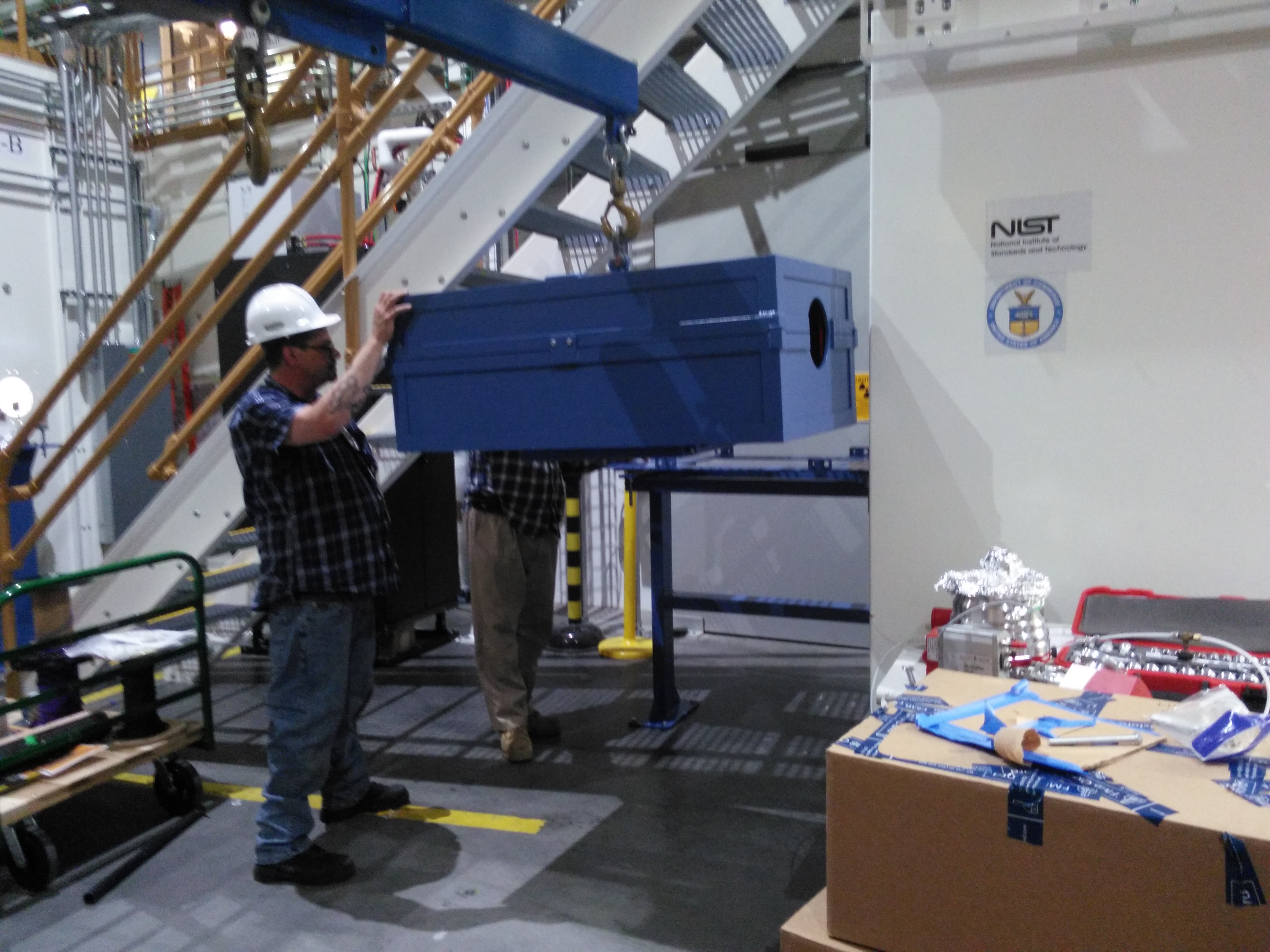
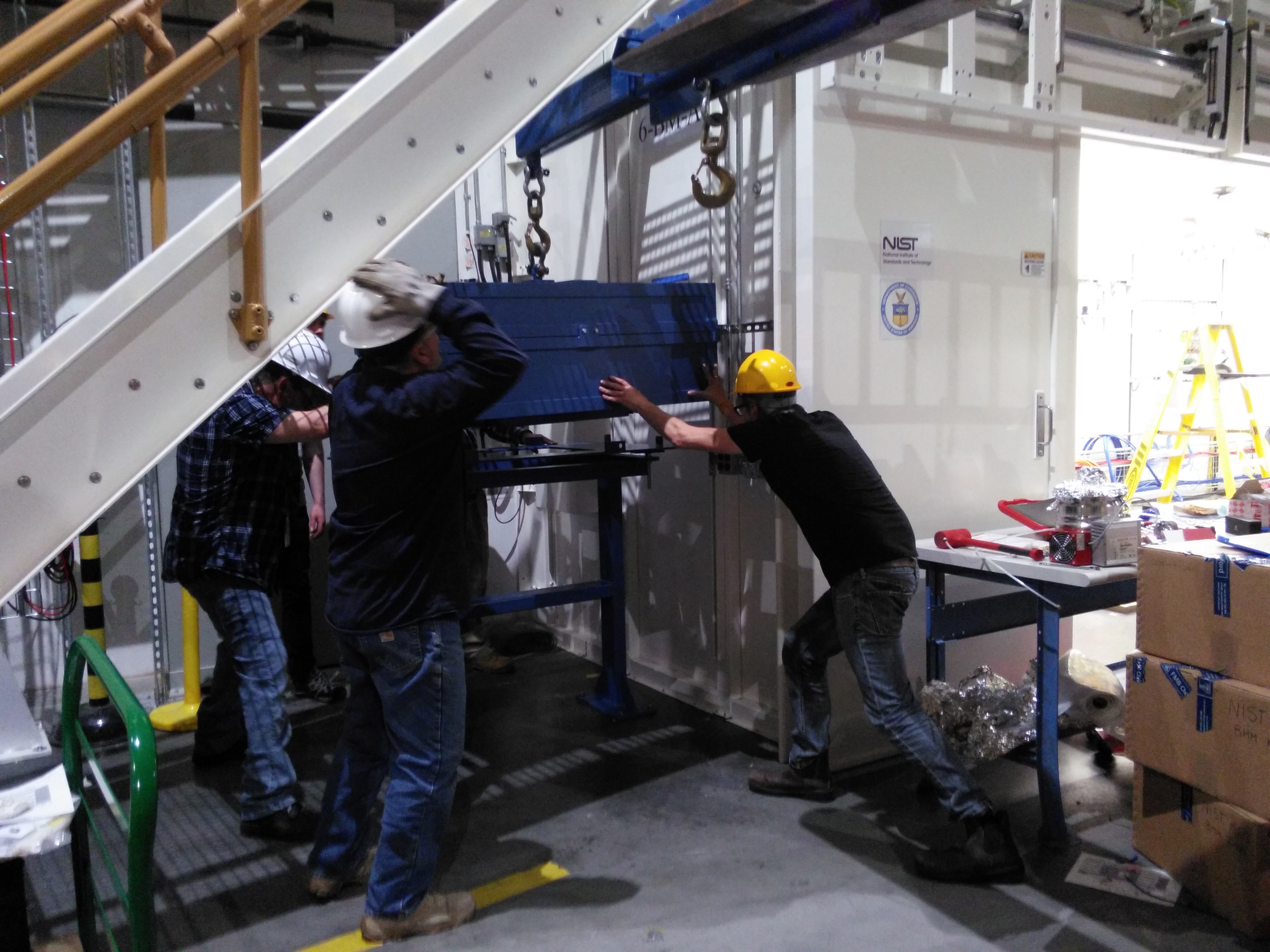
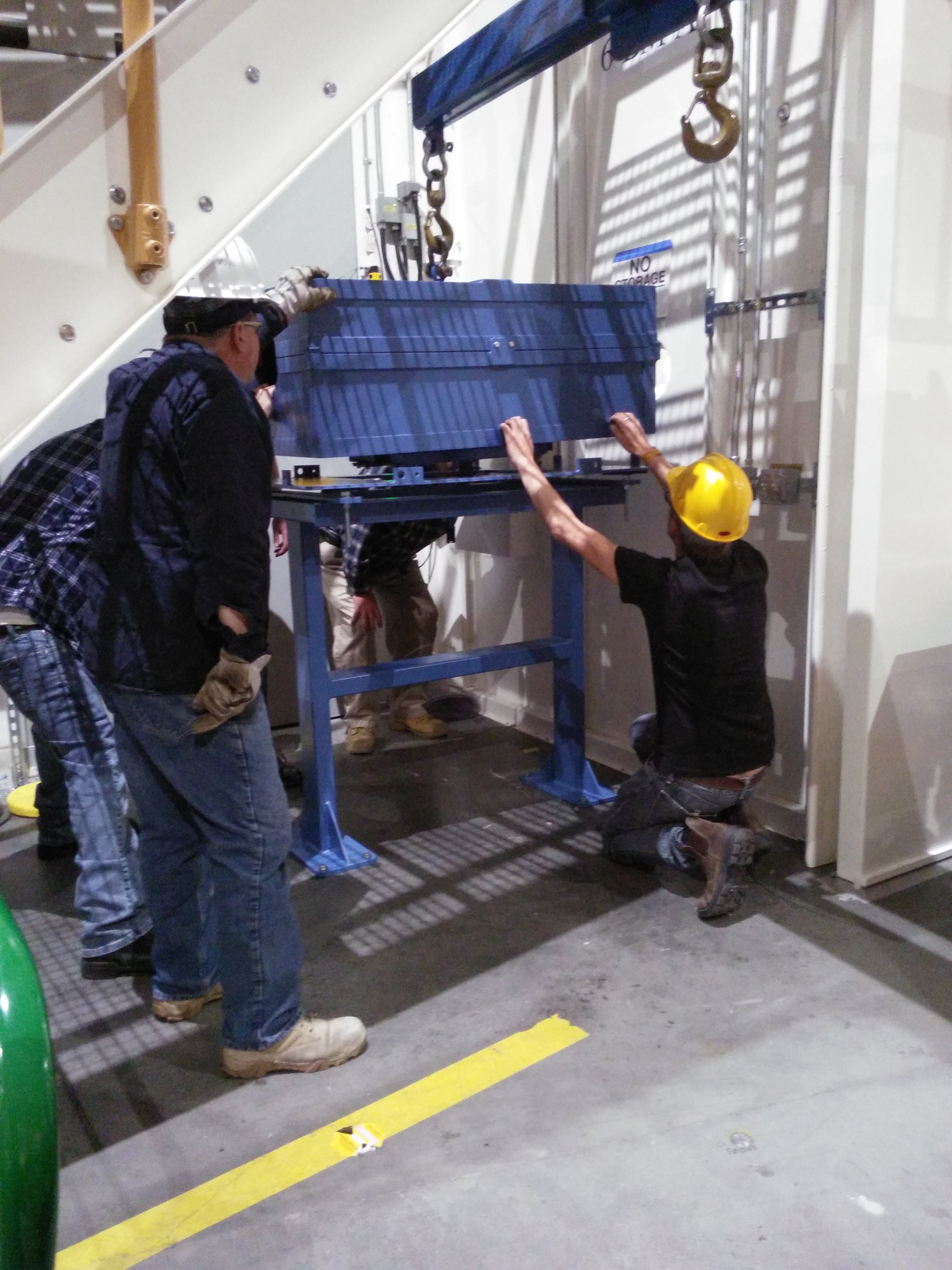
The box is then jockeyed into position on the stand. This thing weights a lot!
| Positioning | Lifting | Getting there | Close | Just about! |
 |
 |
 |
 |
 |
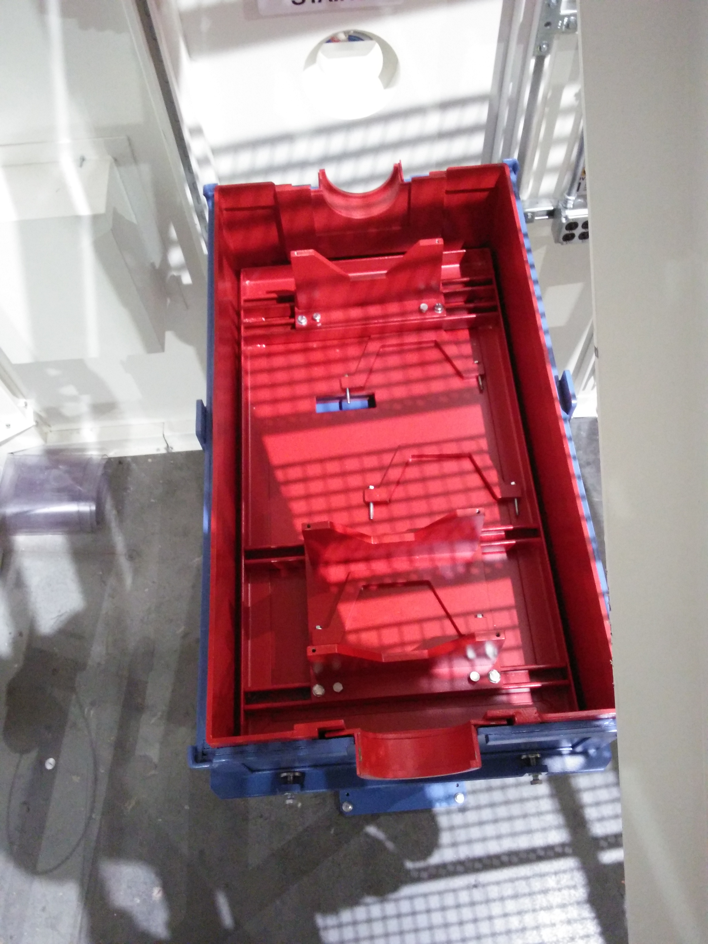
The pump vessel and the secondary stand are now ready for the transport pipe. The red-painted parts are lead, the blue are steel.
| Empty shielded box. | Secondary stand |
 |
 |
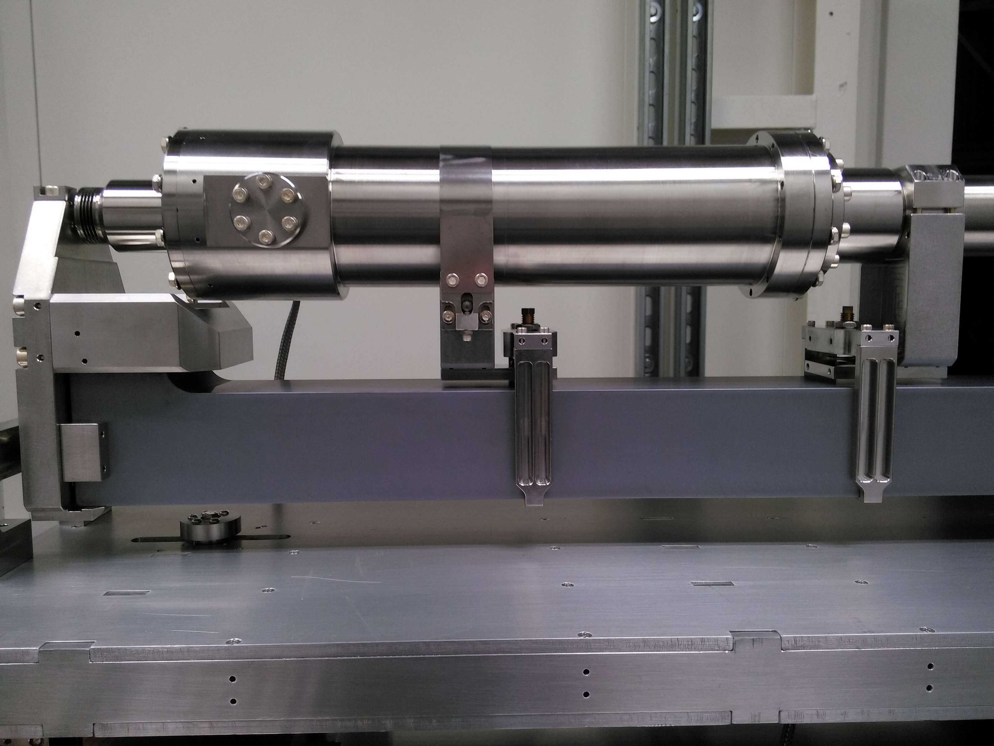
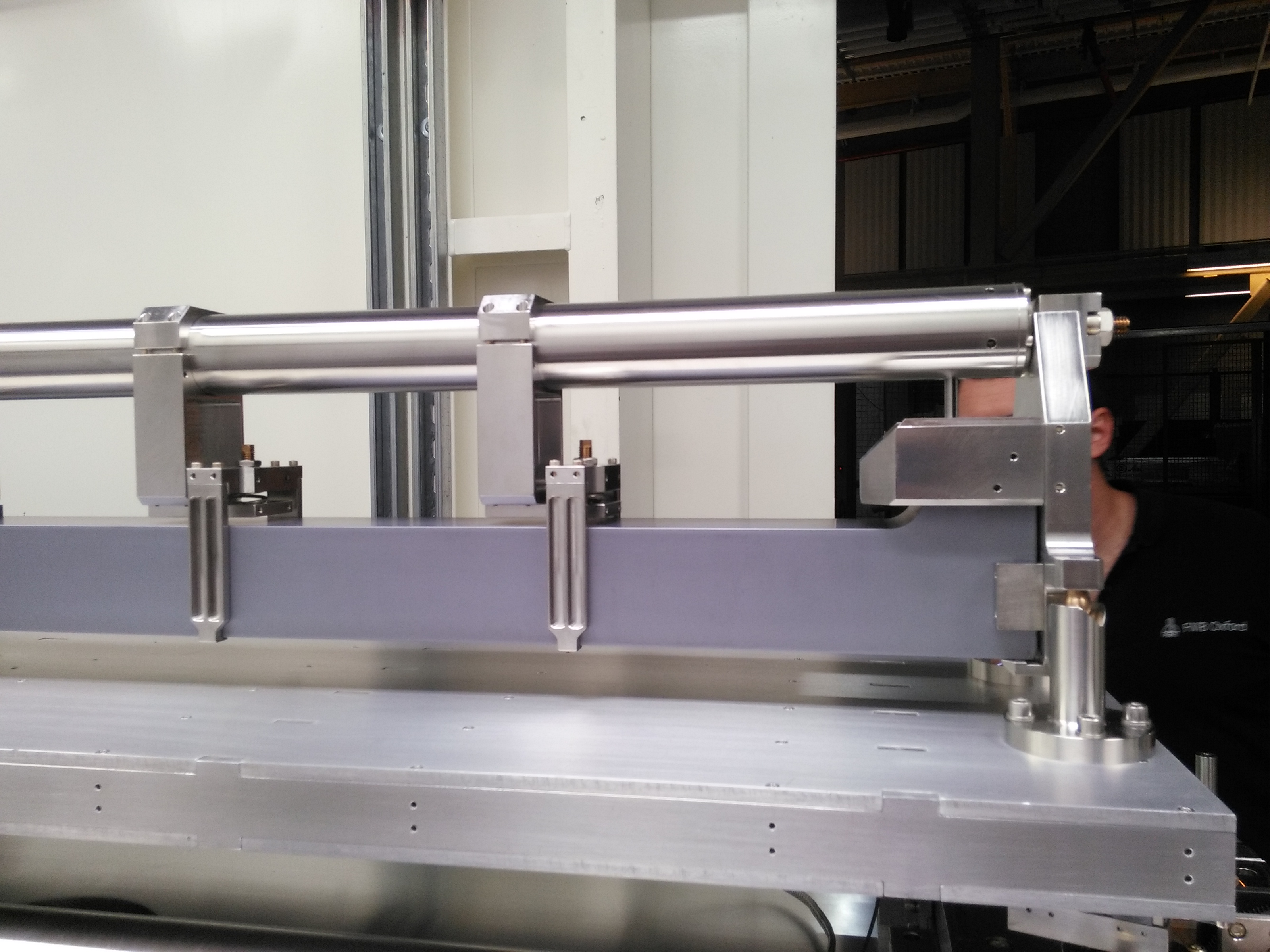
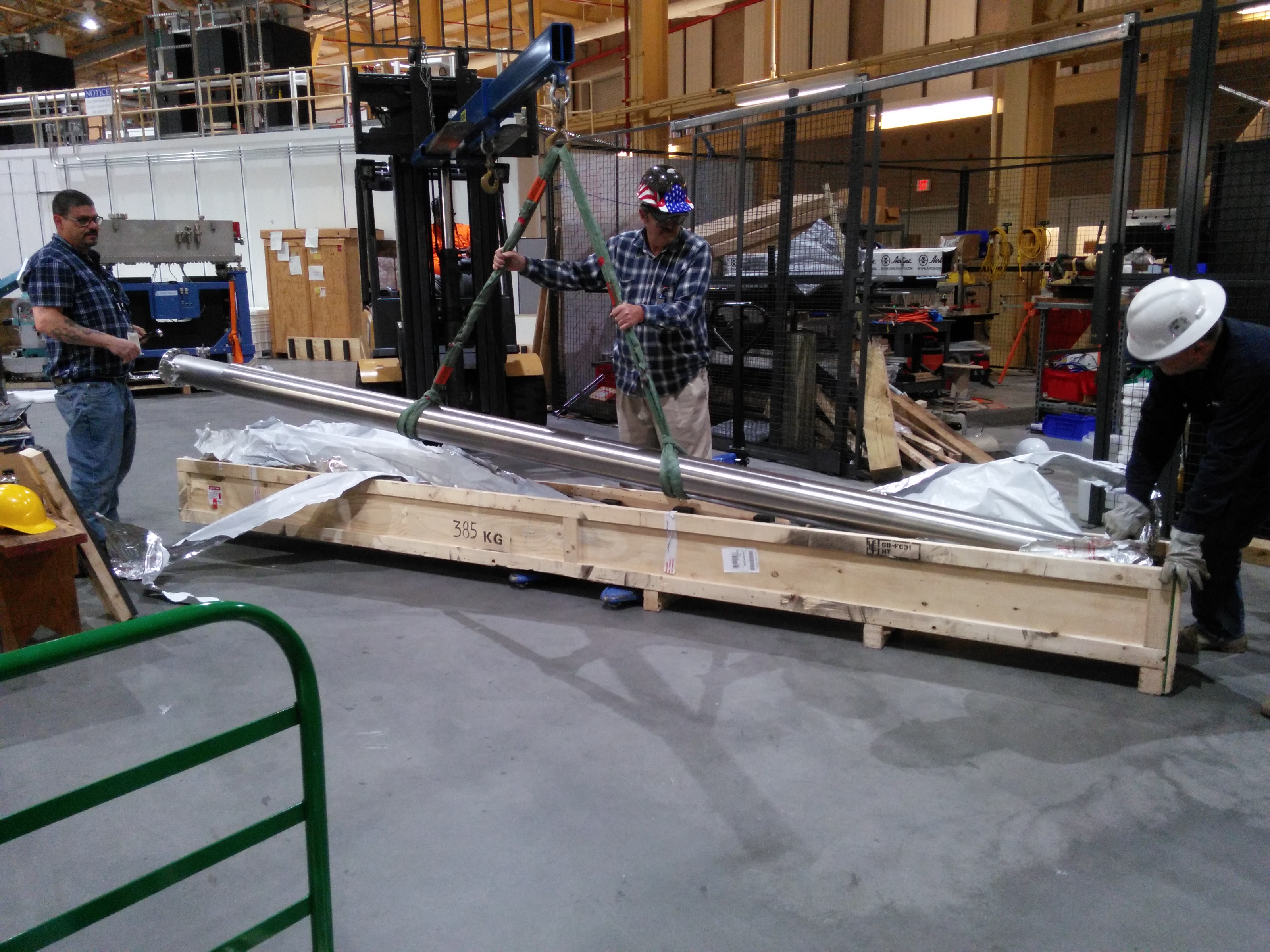
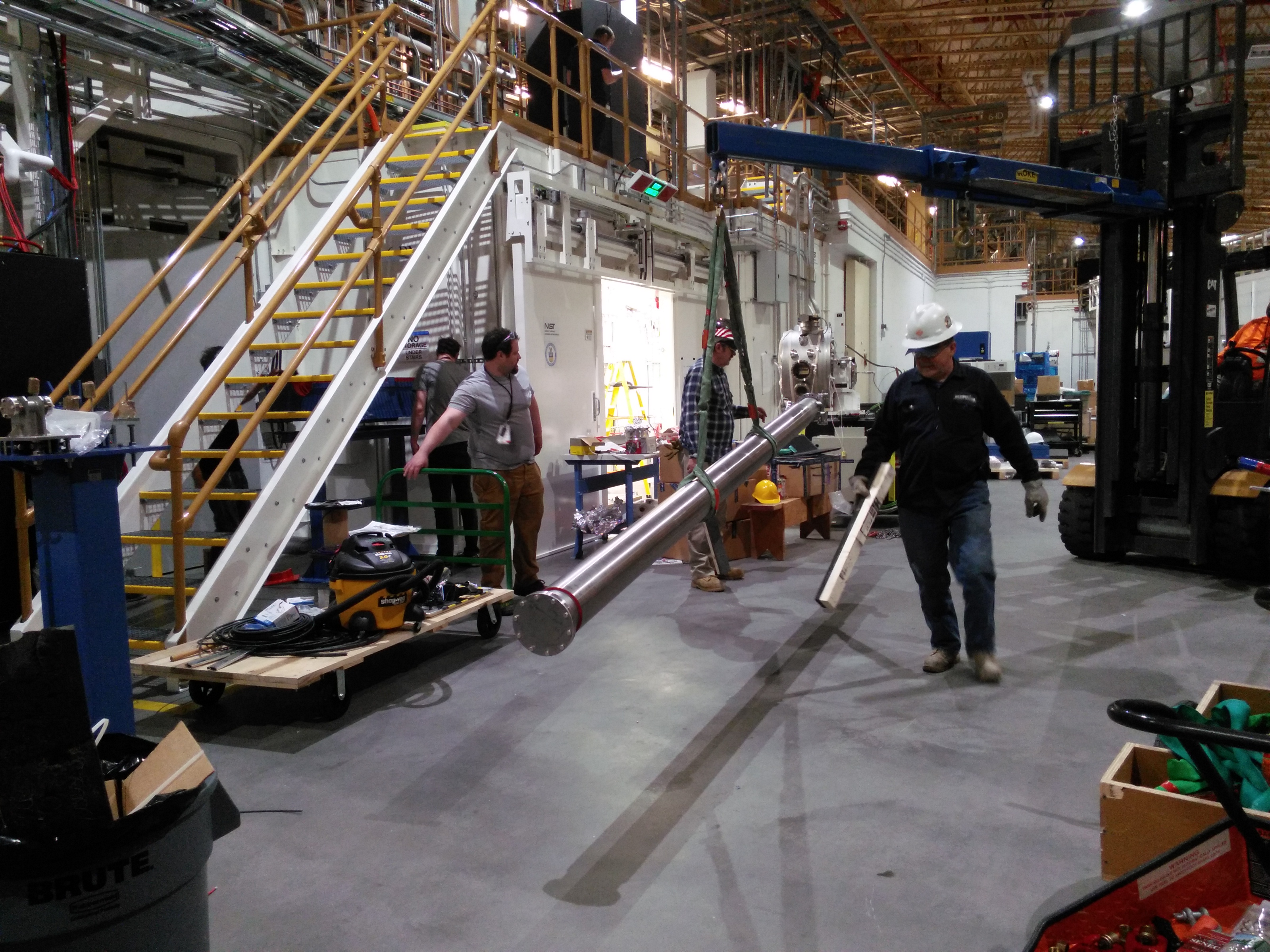
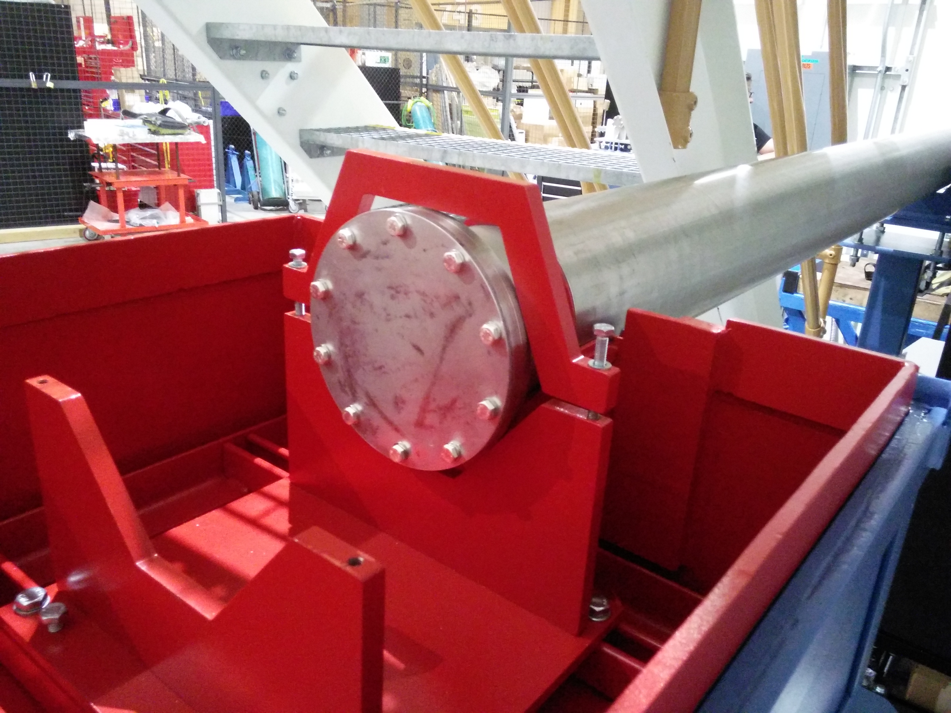
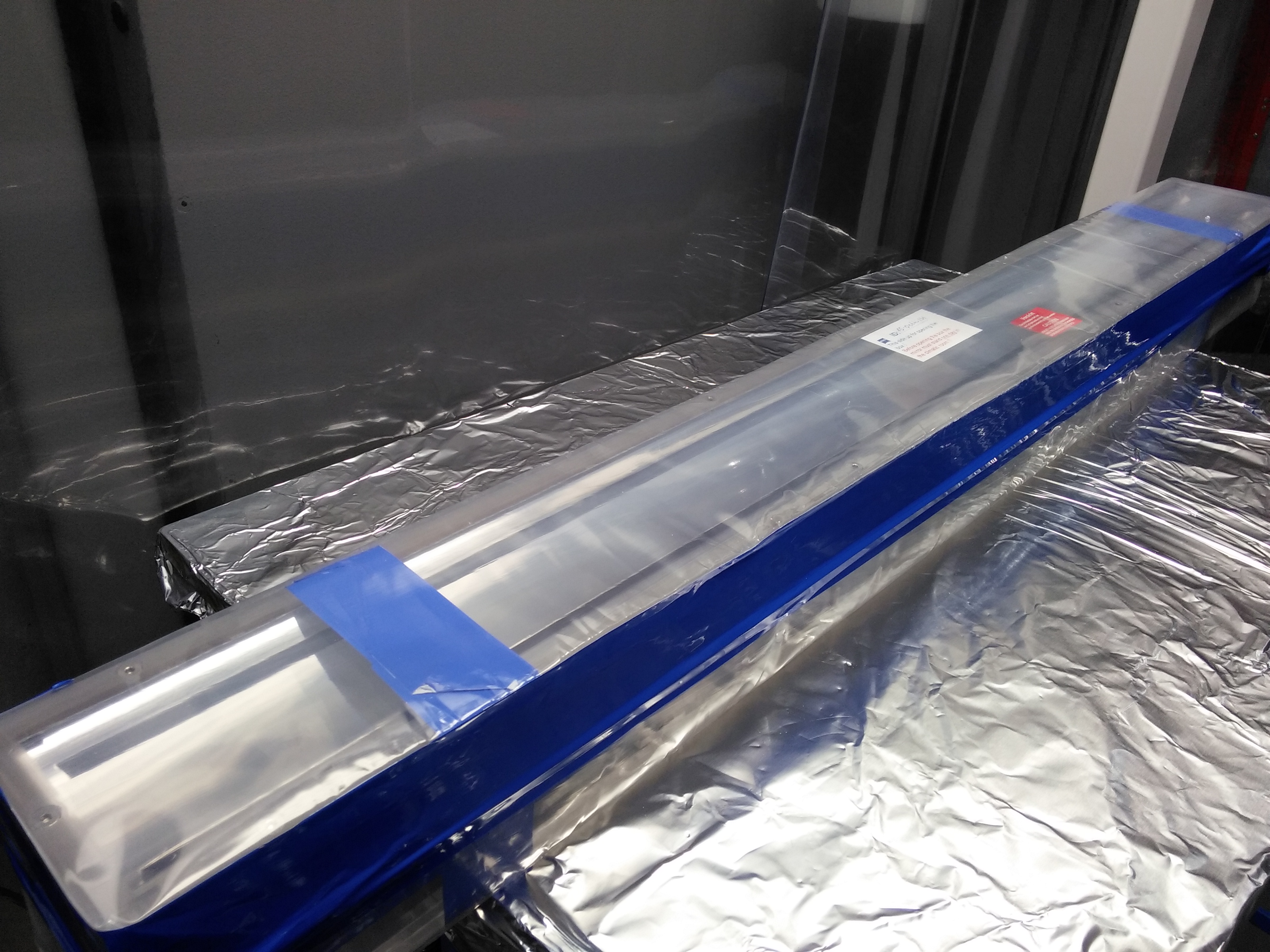
Transport pipe
This is a 6-inch steel tube with lead shielding wrapped around it. It weights about 370 kg/800 pounds.
| Remove the trasport from the shipping container | Carrying | Lifting |
 |
 |
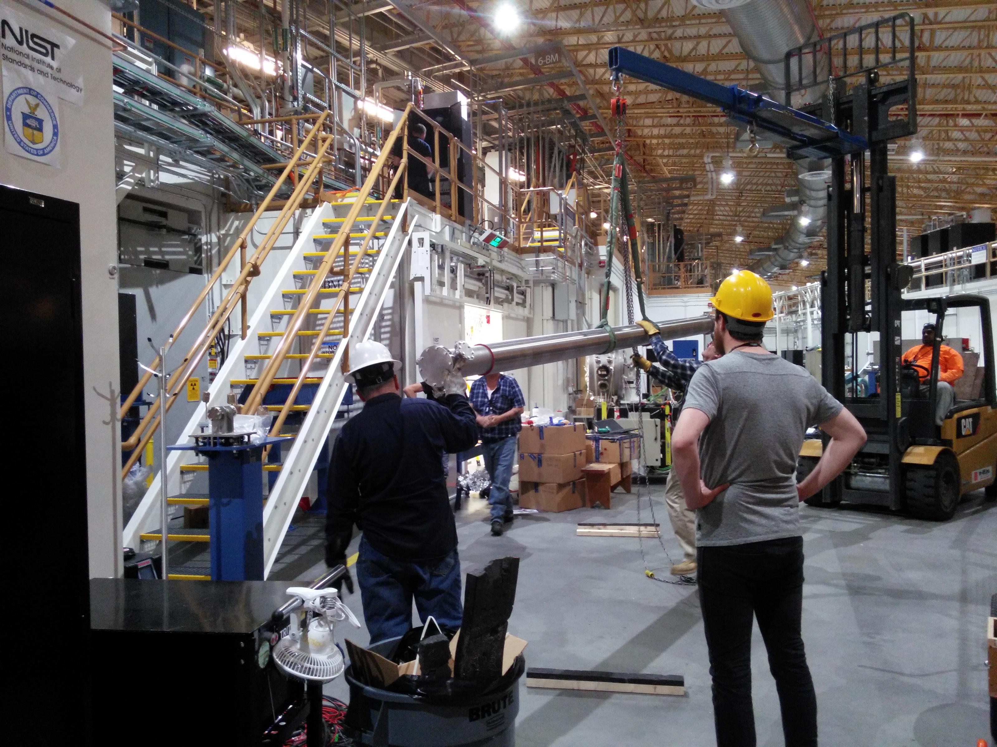 |
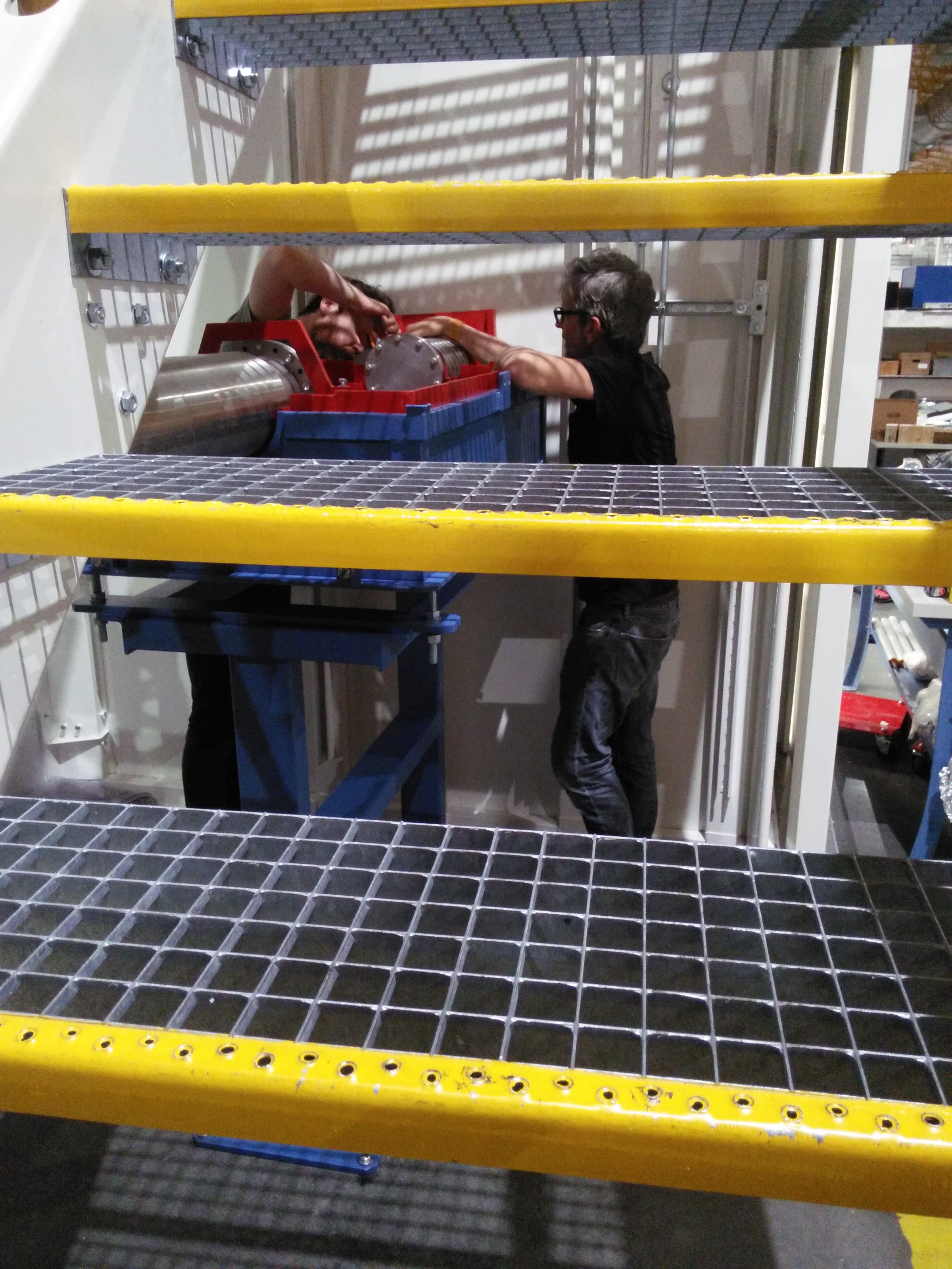
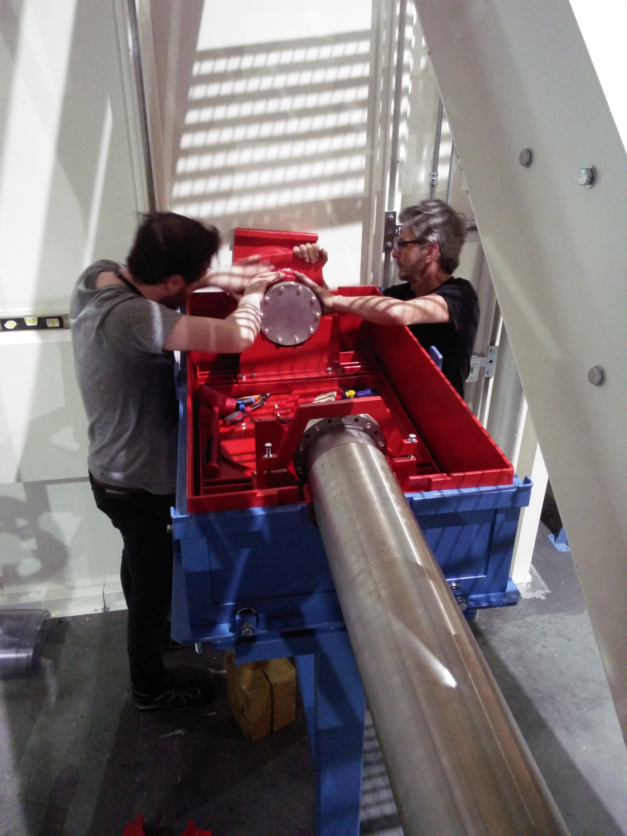
At this point, I had to run away to make a presentation about BMM to the Radiation Safety Committee. When I returned, the transport pipe was in place.
| Transport pipe protruding into the end station | Pipe resting on a collette in the shielded box | Ian and Beau work on attaching the lead collers to pipe | It was a difficult job |
 |
 |
 |
 |
December 20, 2016
M1 assembly
| Looking down the length of M1 | Working on M1 |
 |
 |
December 16, 2016
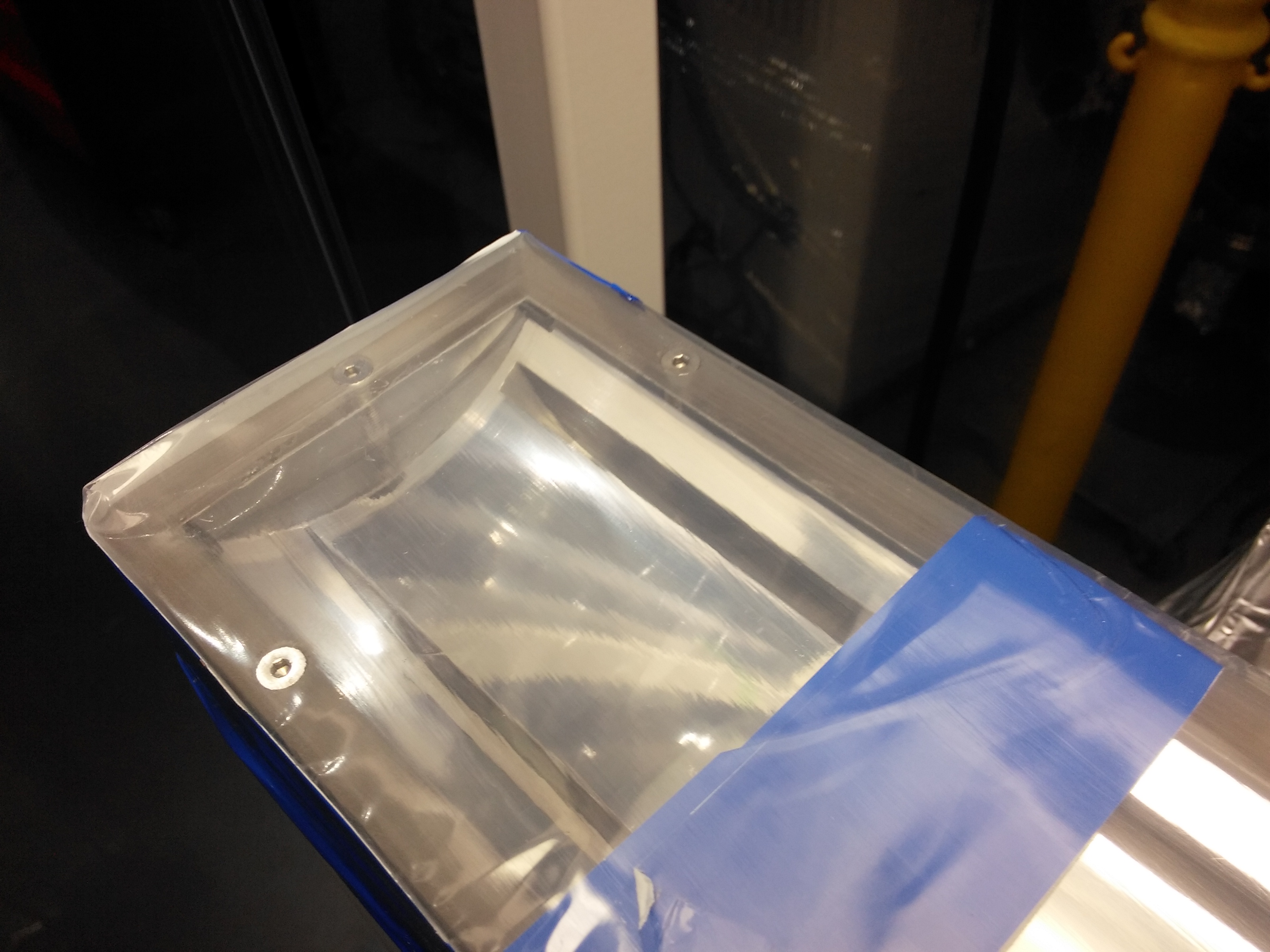
The collimating mirror (M1) and the front end are being installed this week.
The M1 optic
| The entire optic | Close up showing the saggital curvature |
 |
 |
M1 installed in the front end
In these photos, M1 is open with the vessel lid supported by rods so that the optic can be installed.
| M1 from upstream | M1 from the inboard side | M1 from downstream |
 |
 |
 |
The front end, partially installed
| Slits and masks | Transport pipe | M1 | Partial assembly, upstream of mirror | Closeup of slits | Ratchet wall |
 |
 |
 |
 |
 |
 |
December 14, 2016
I went to the APS for a week of experiments. Upon my return A LOT of stuff had happened! M1 and front end installation also began. Photos to come.
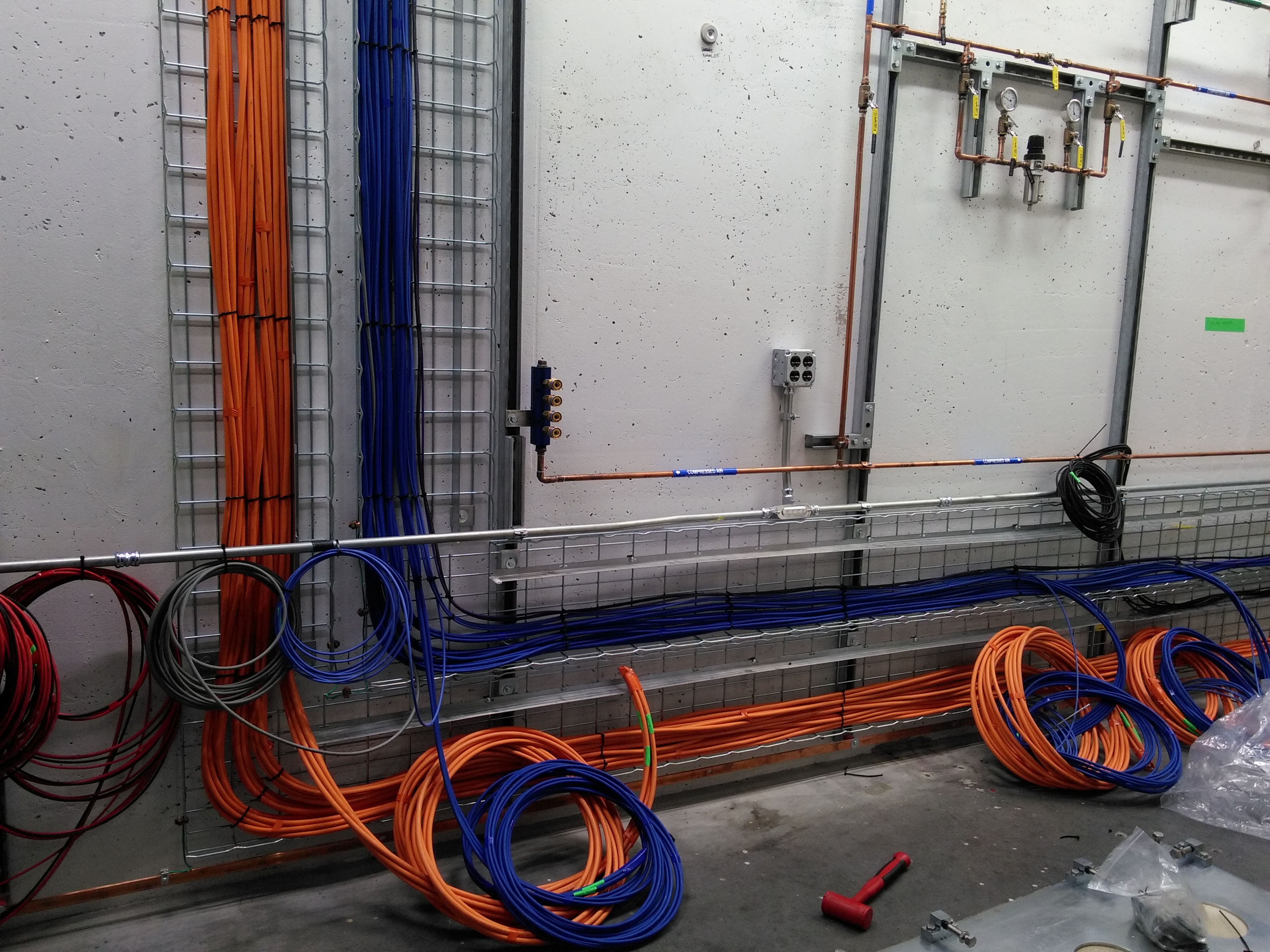
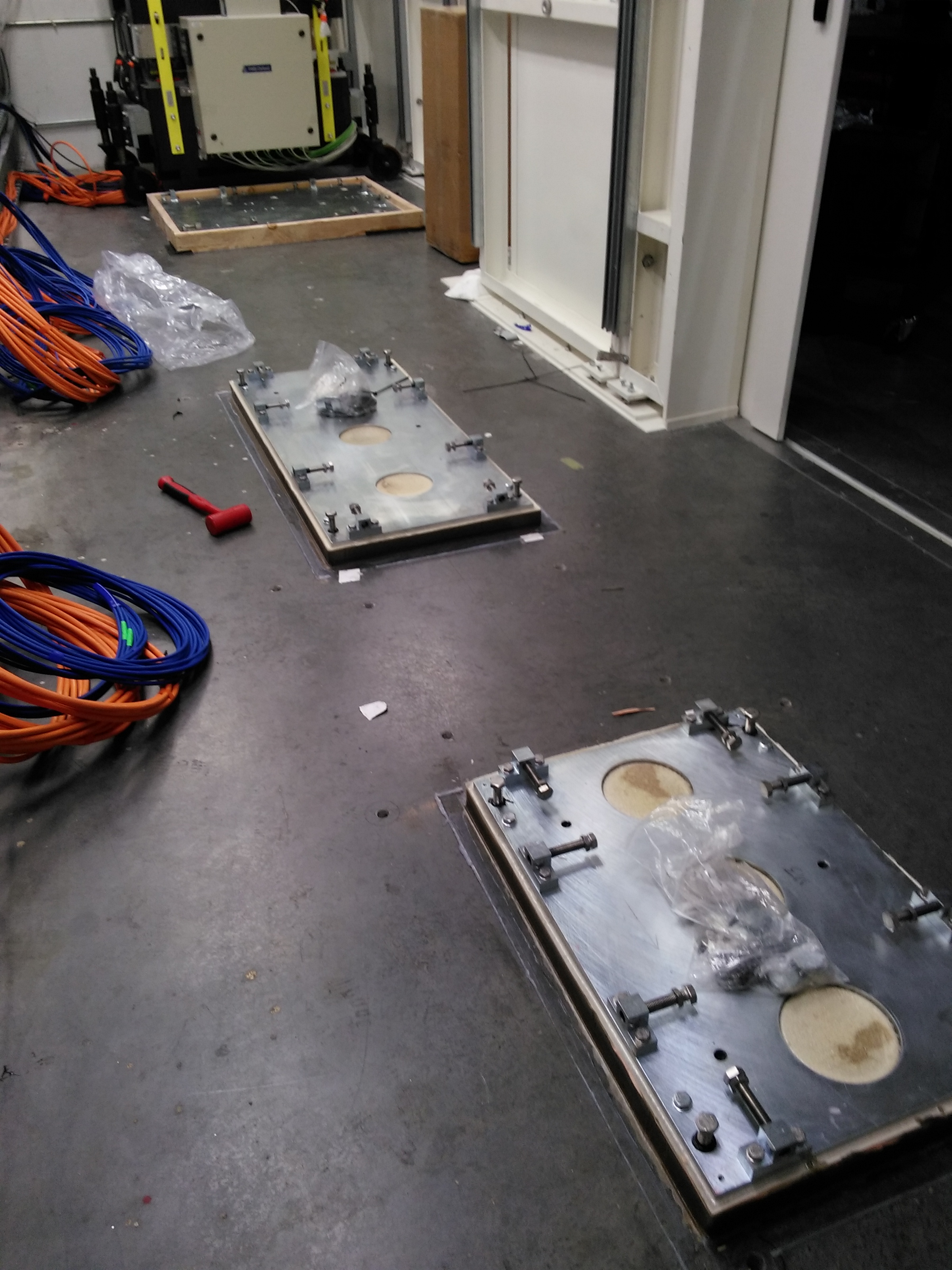
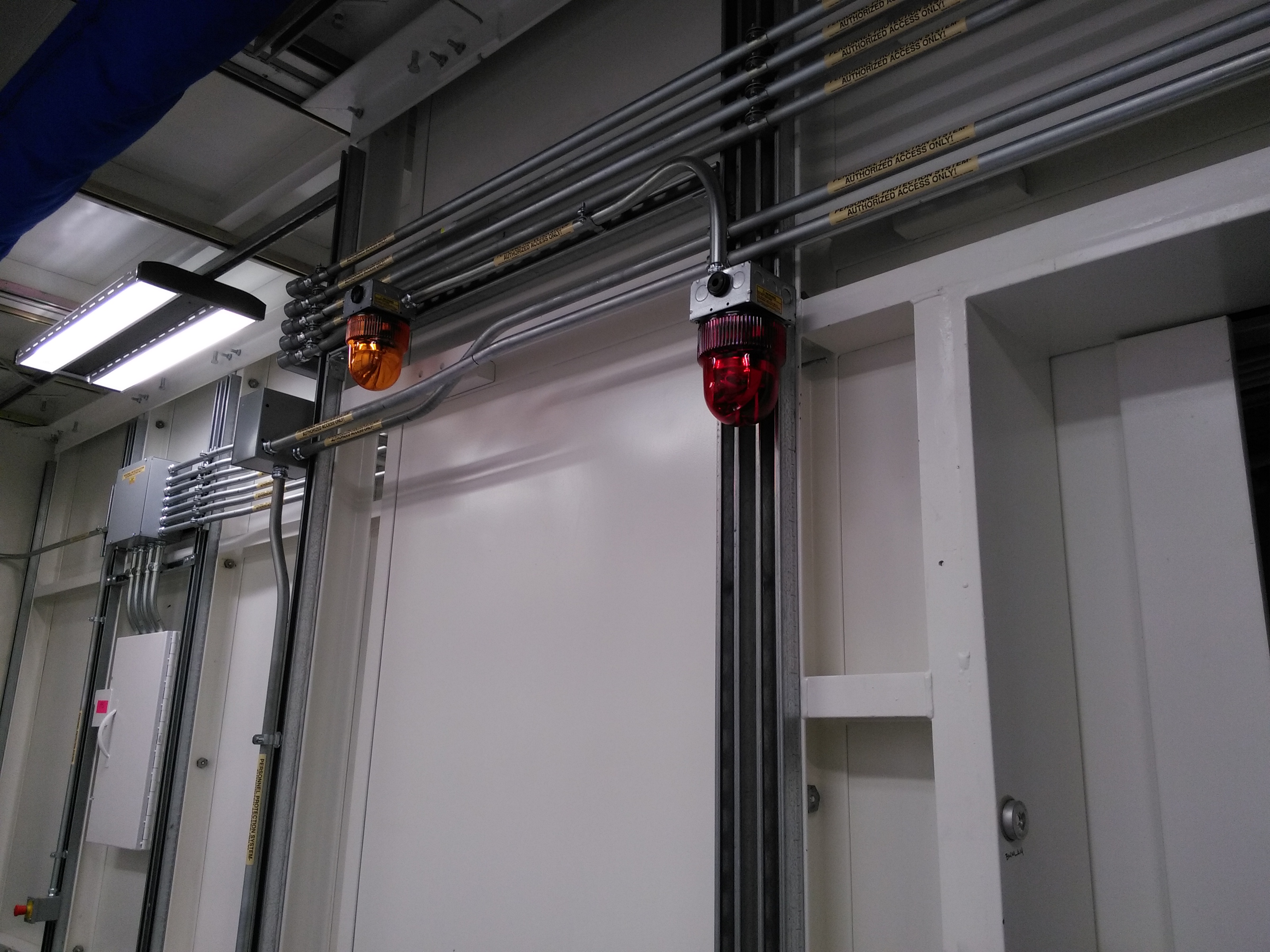
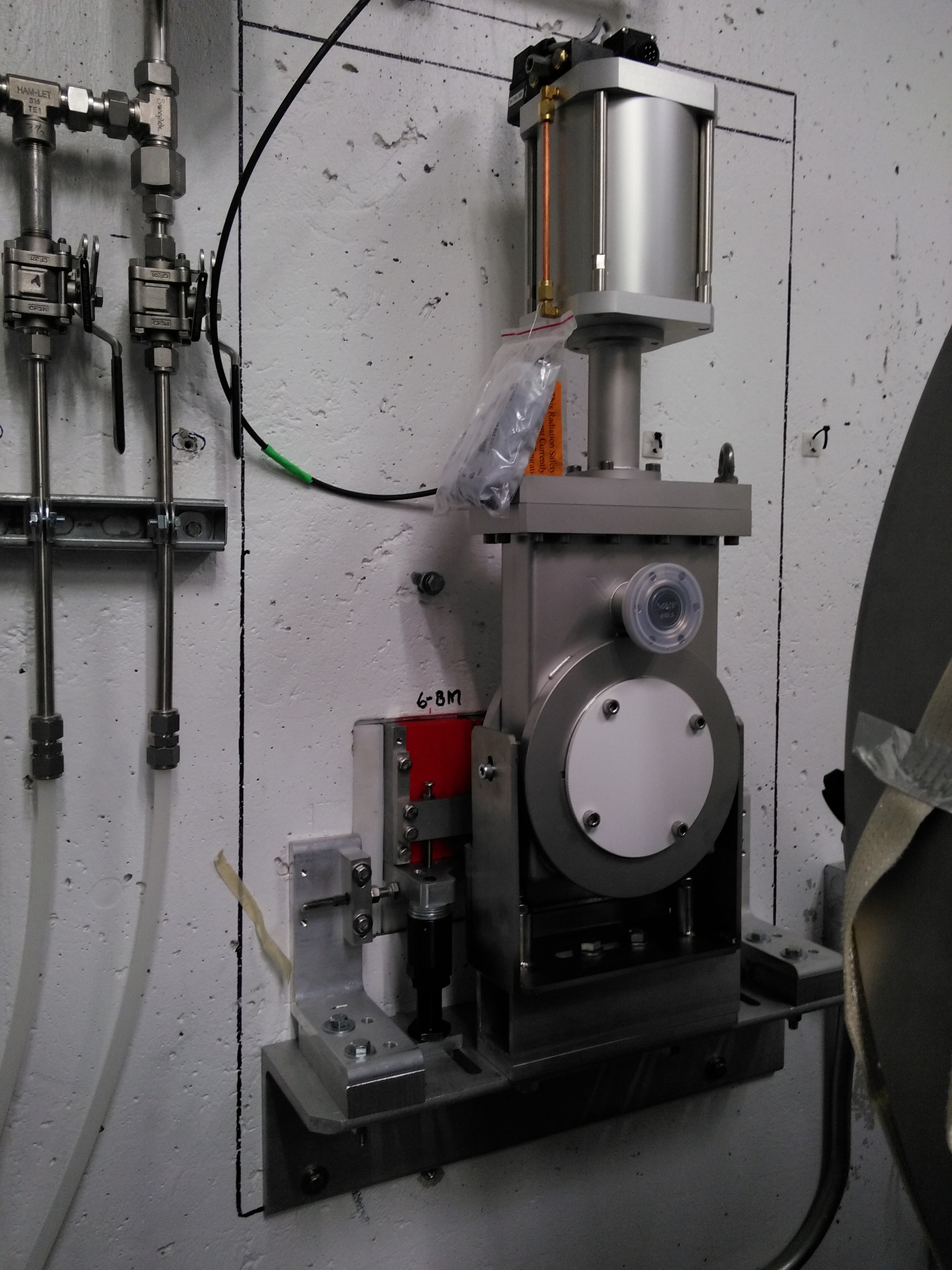
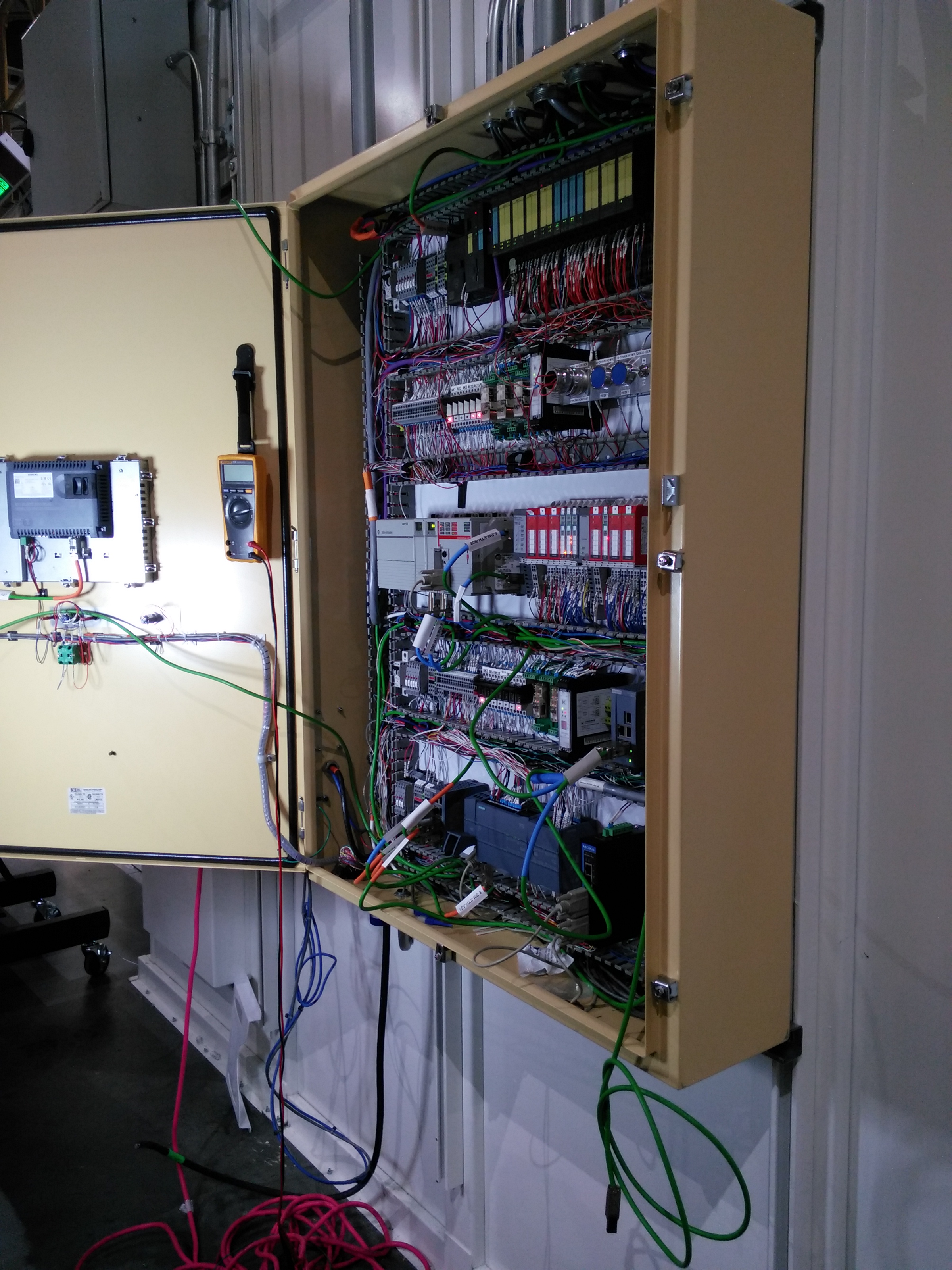
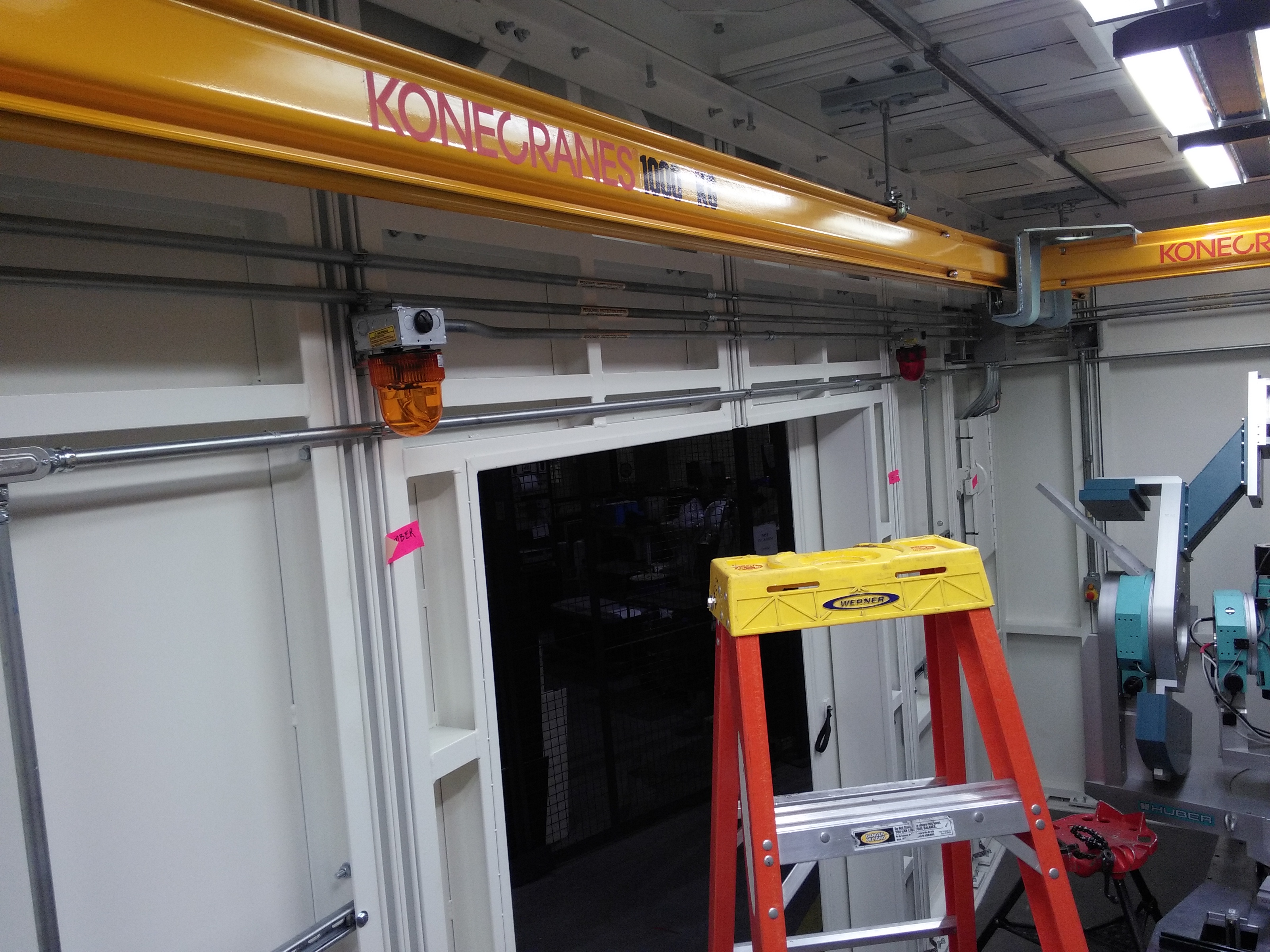
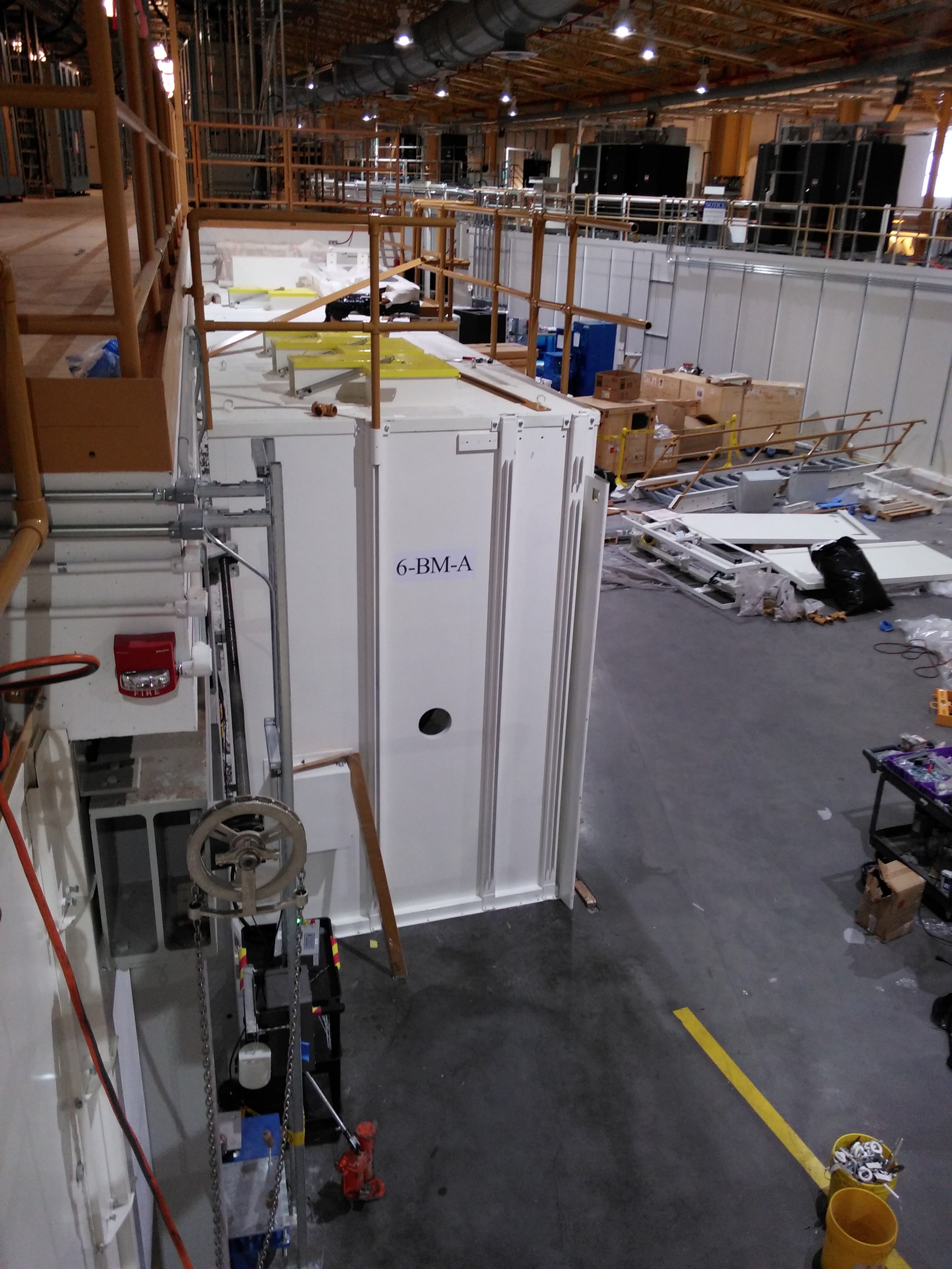
FOE
| Photon shutter at the end of 6BM-A | Cables pulled into 6BM-A | Grouting and base plates for mono and mirrors | Amber and red PPS lights in 6BM-A | Ratchet wall feedthrough + valve | PPS wiring for 6BM-A |
 |
 |
 |
 |
 |
 |
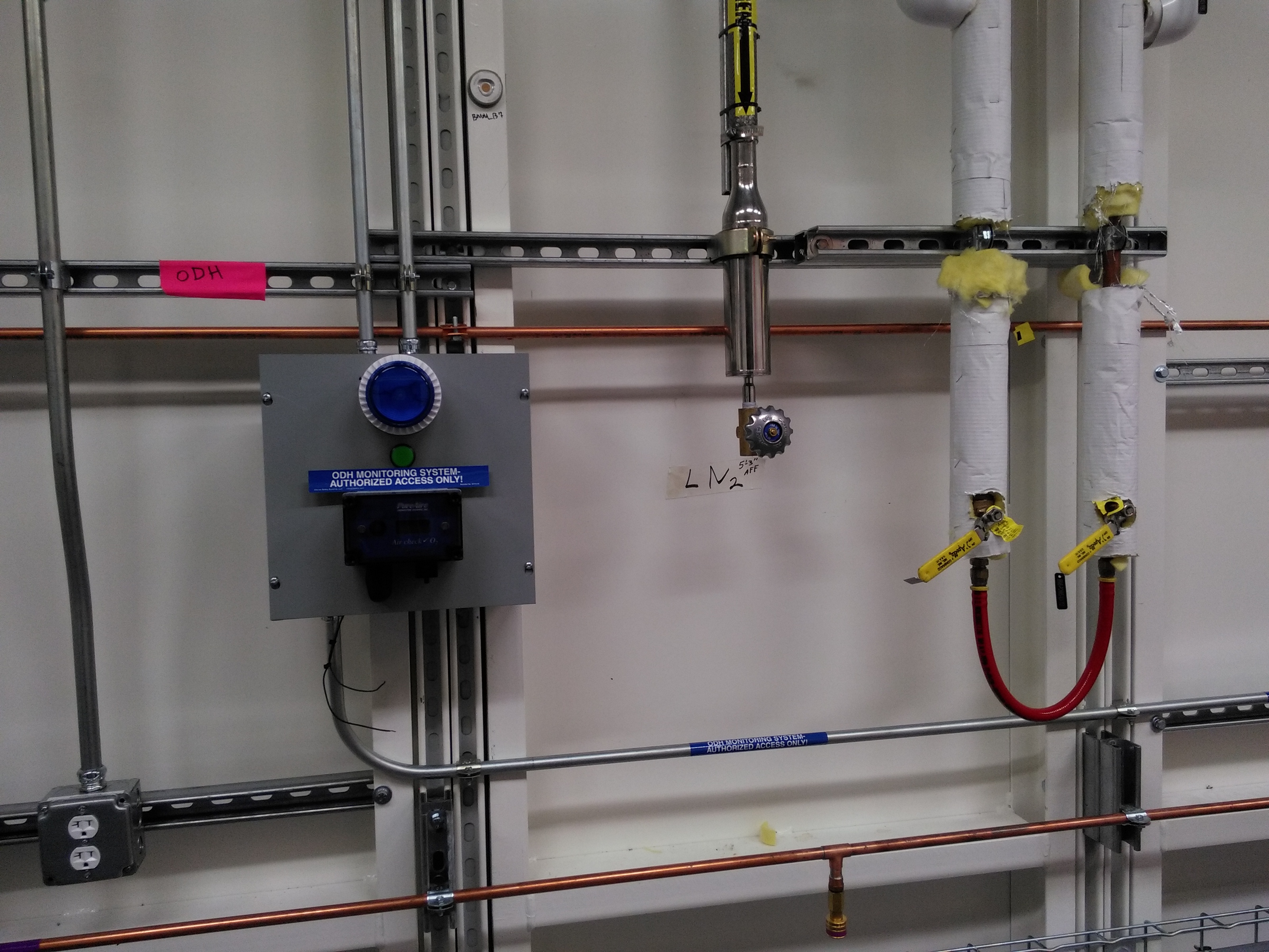
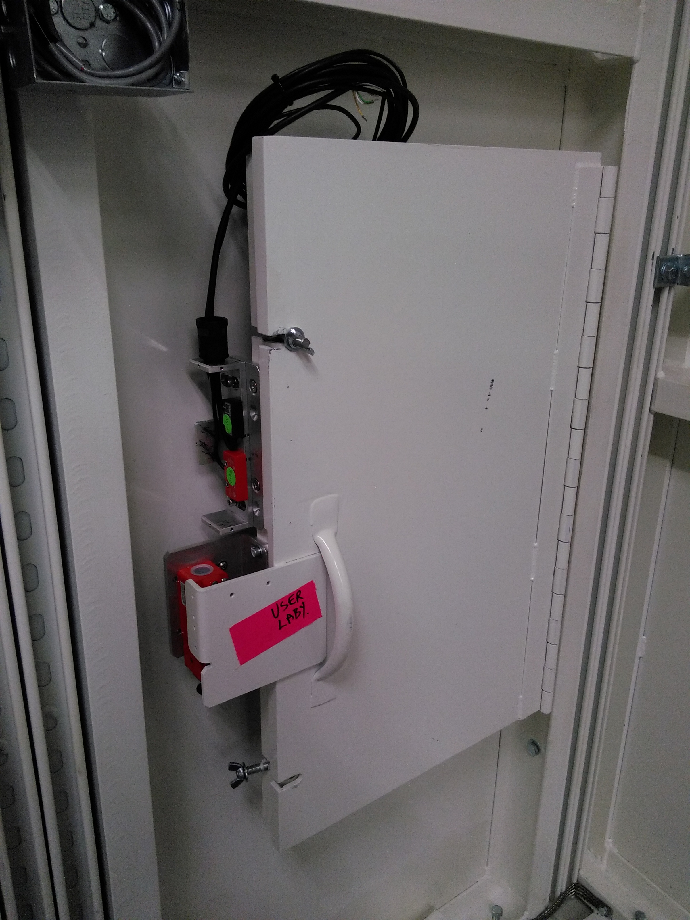
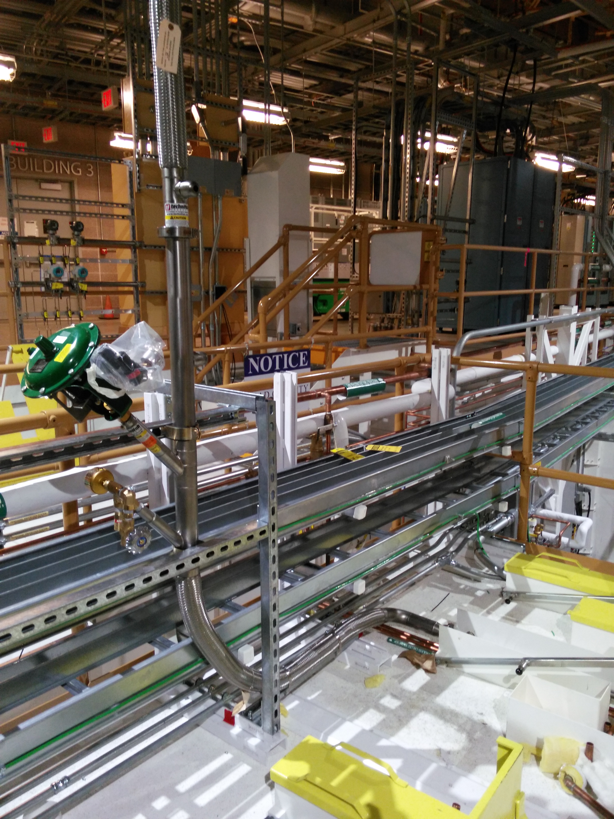
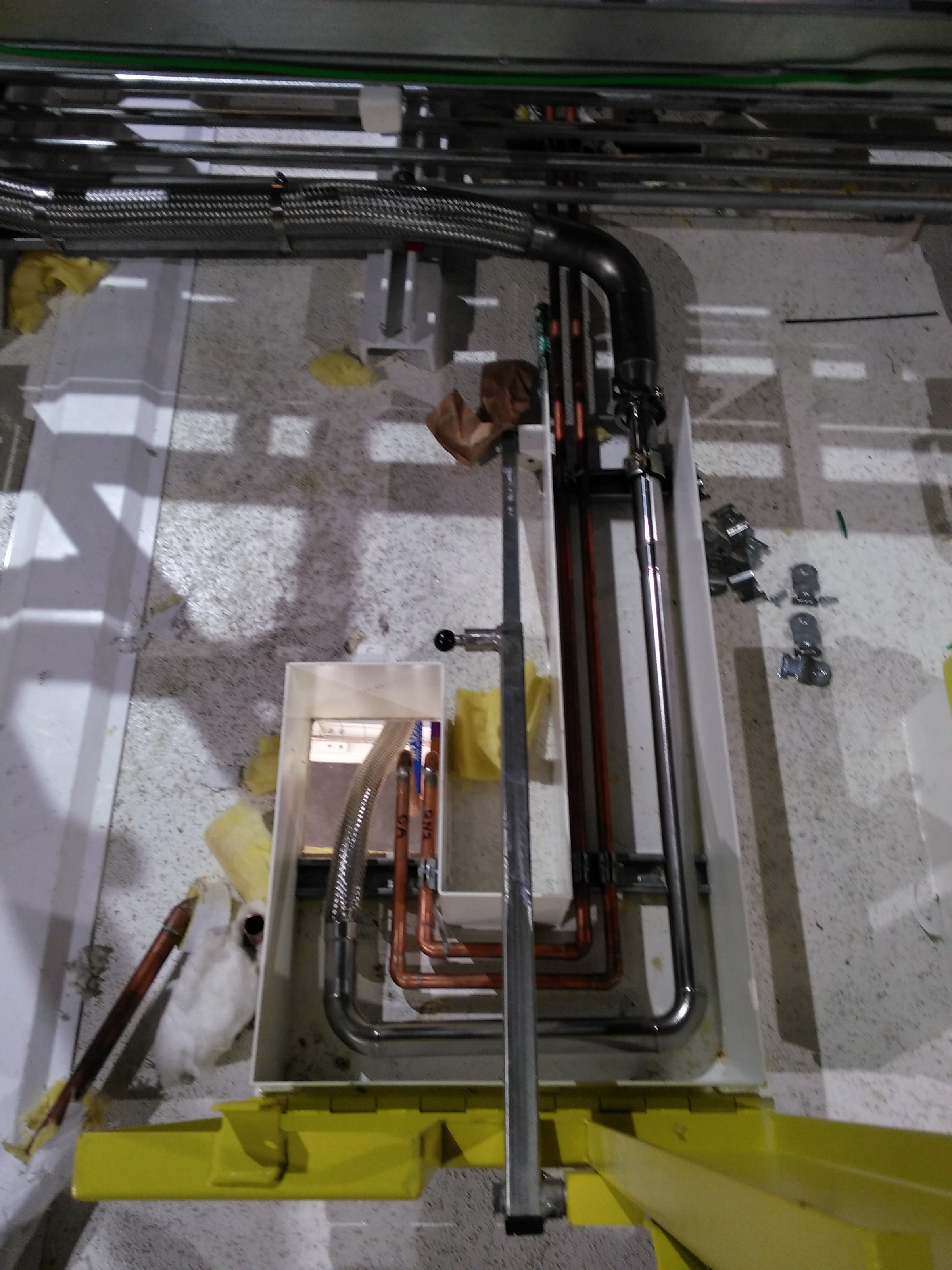
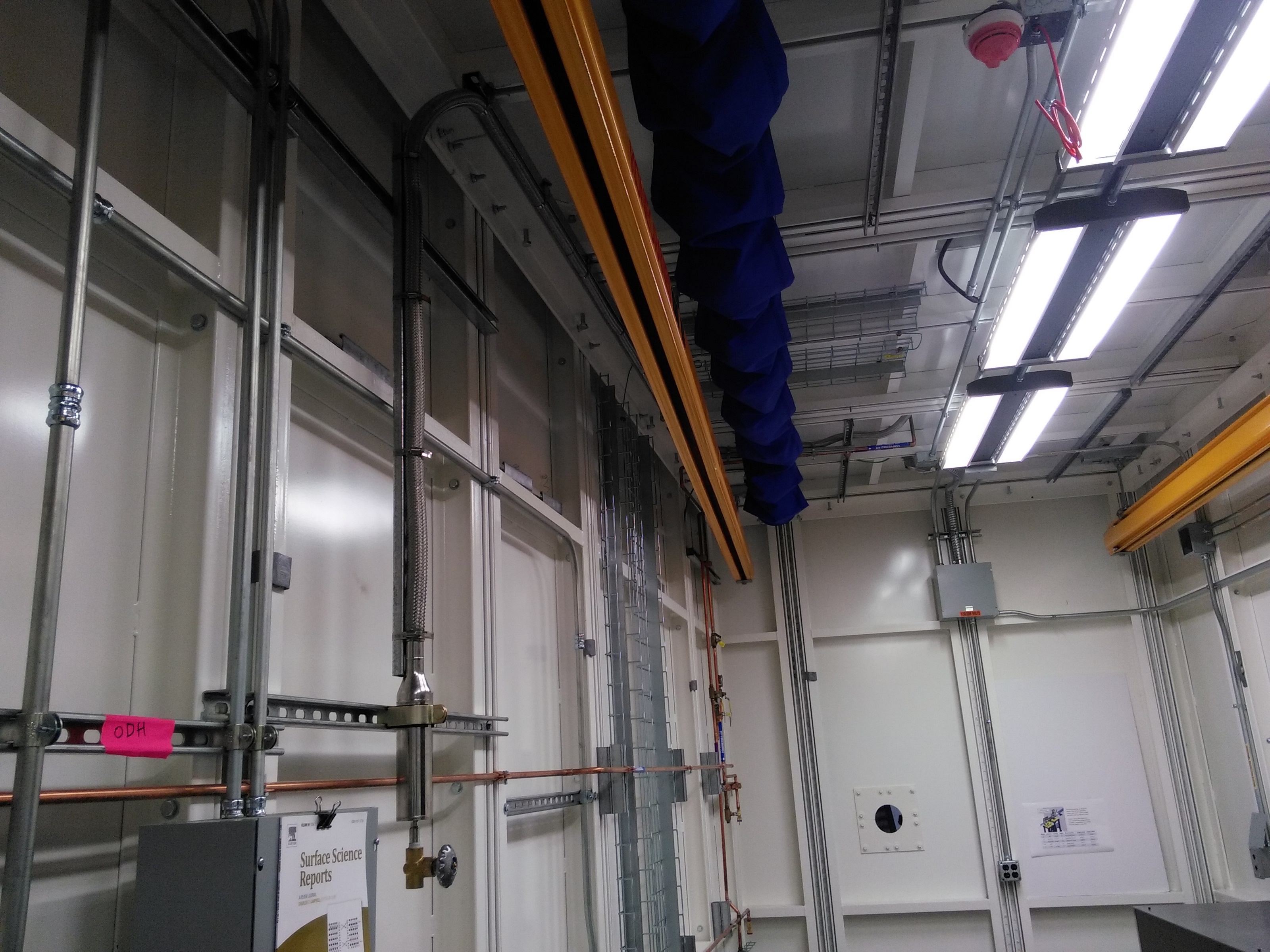
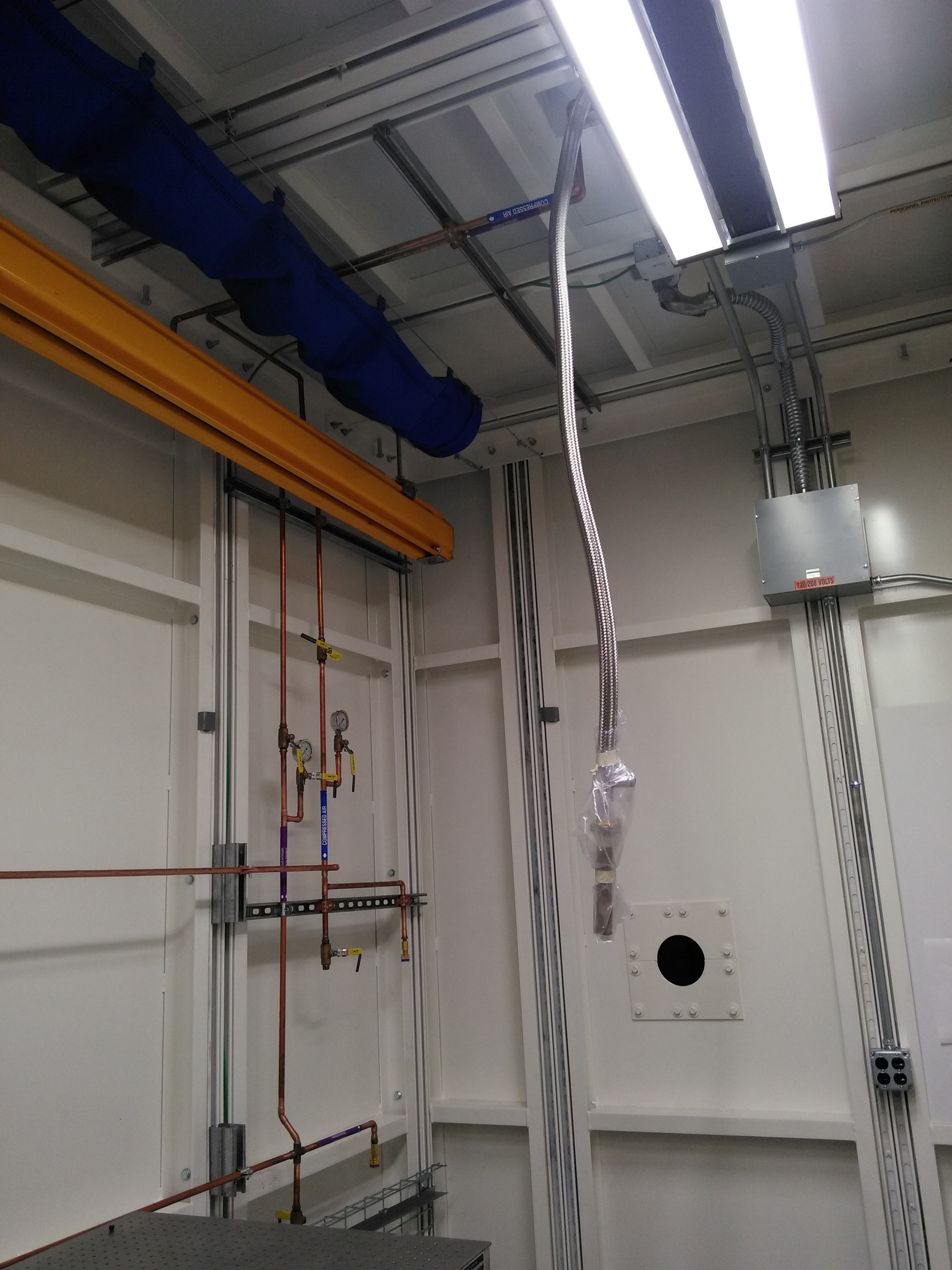
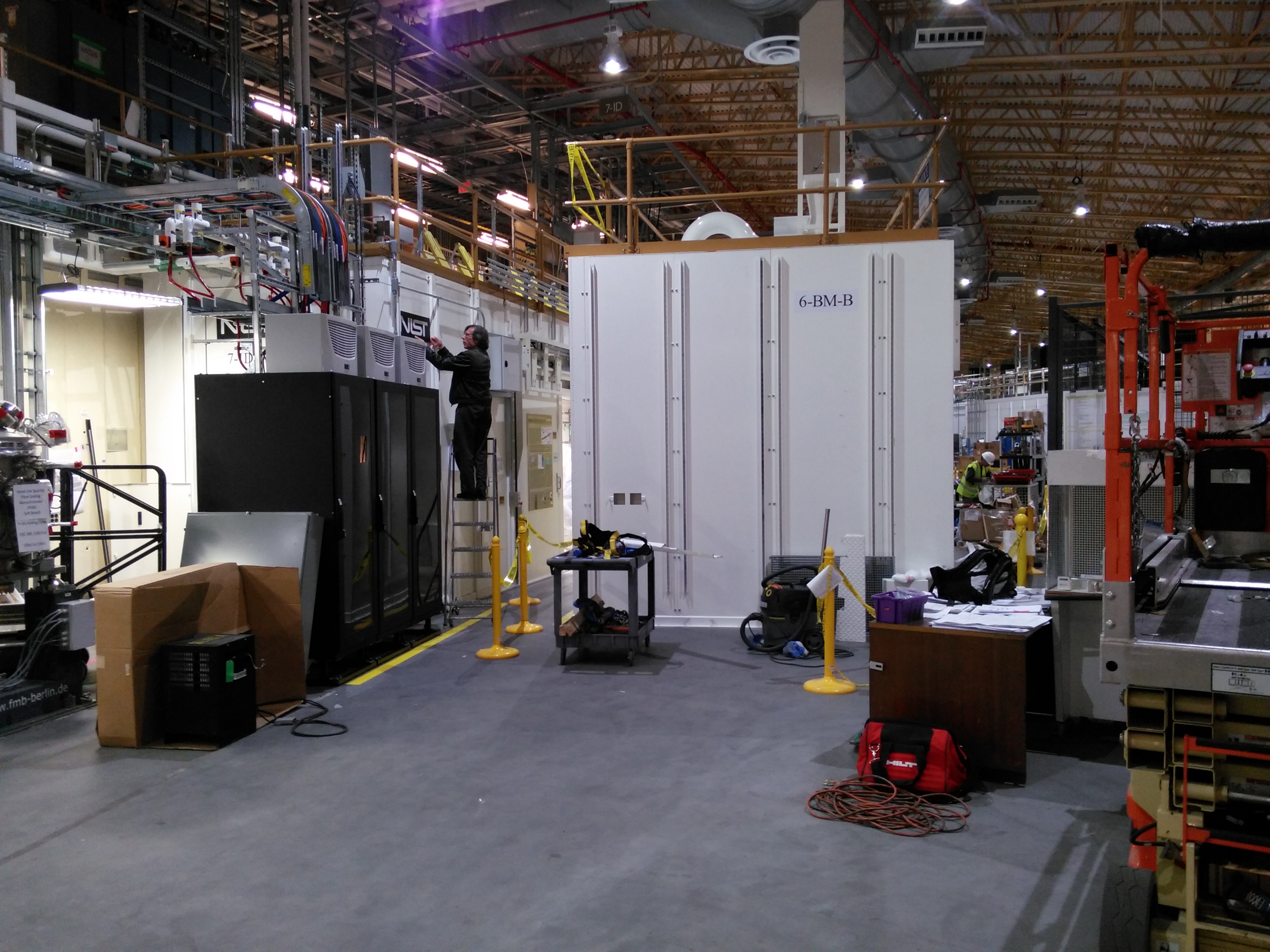
End station
| Amber and red PPS lights in 6BM-B | Oxygen deficiency hazard (ODH) sensor in 6BM-B | User labyrynth with PPS switch |
 |
 |
 |
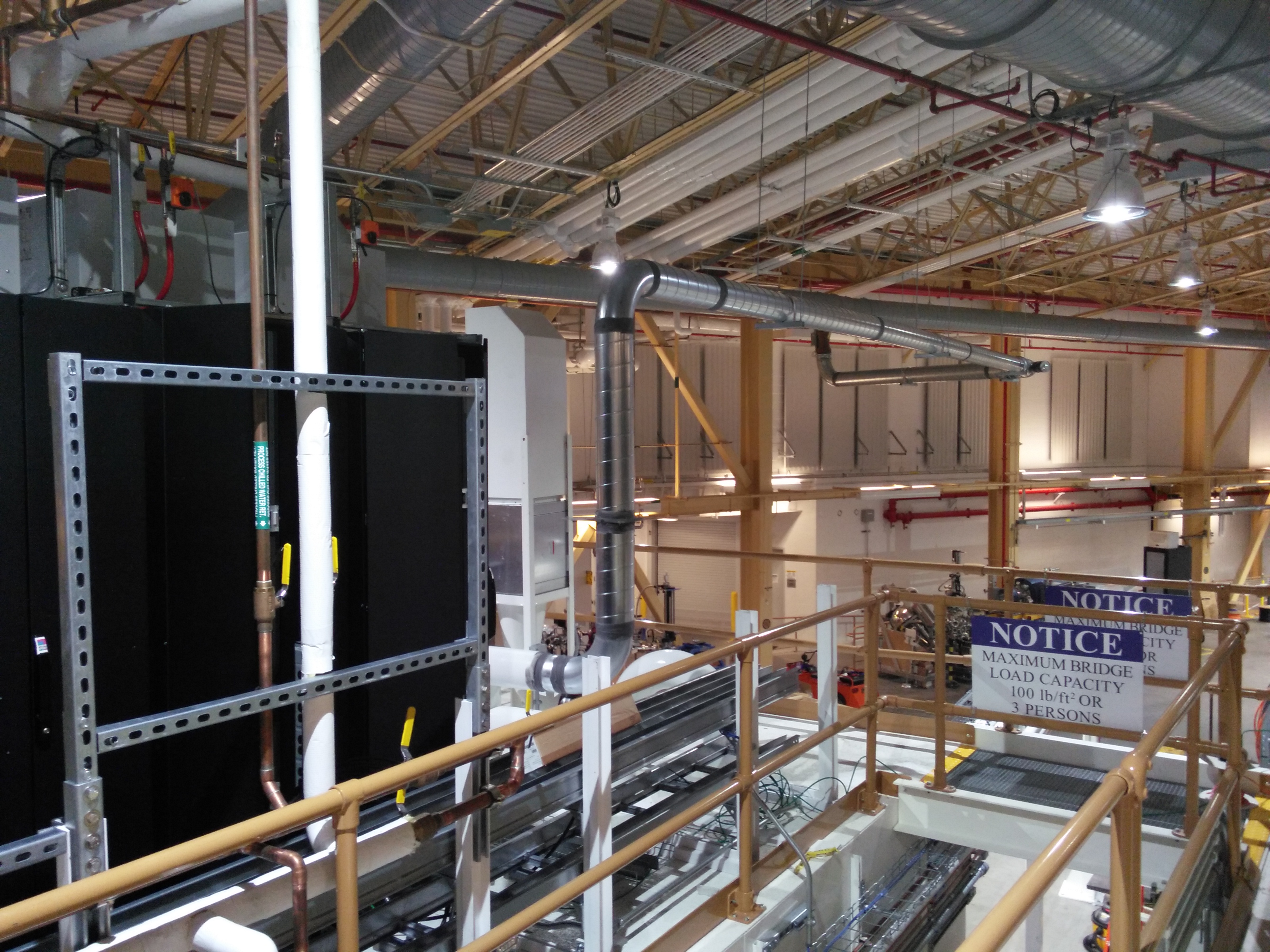
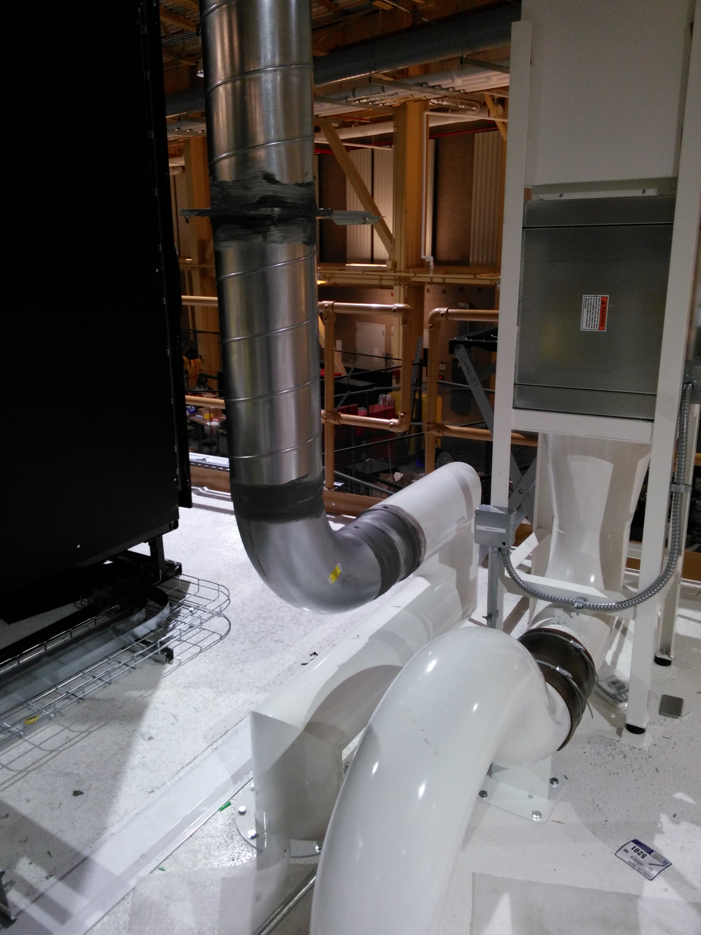
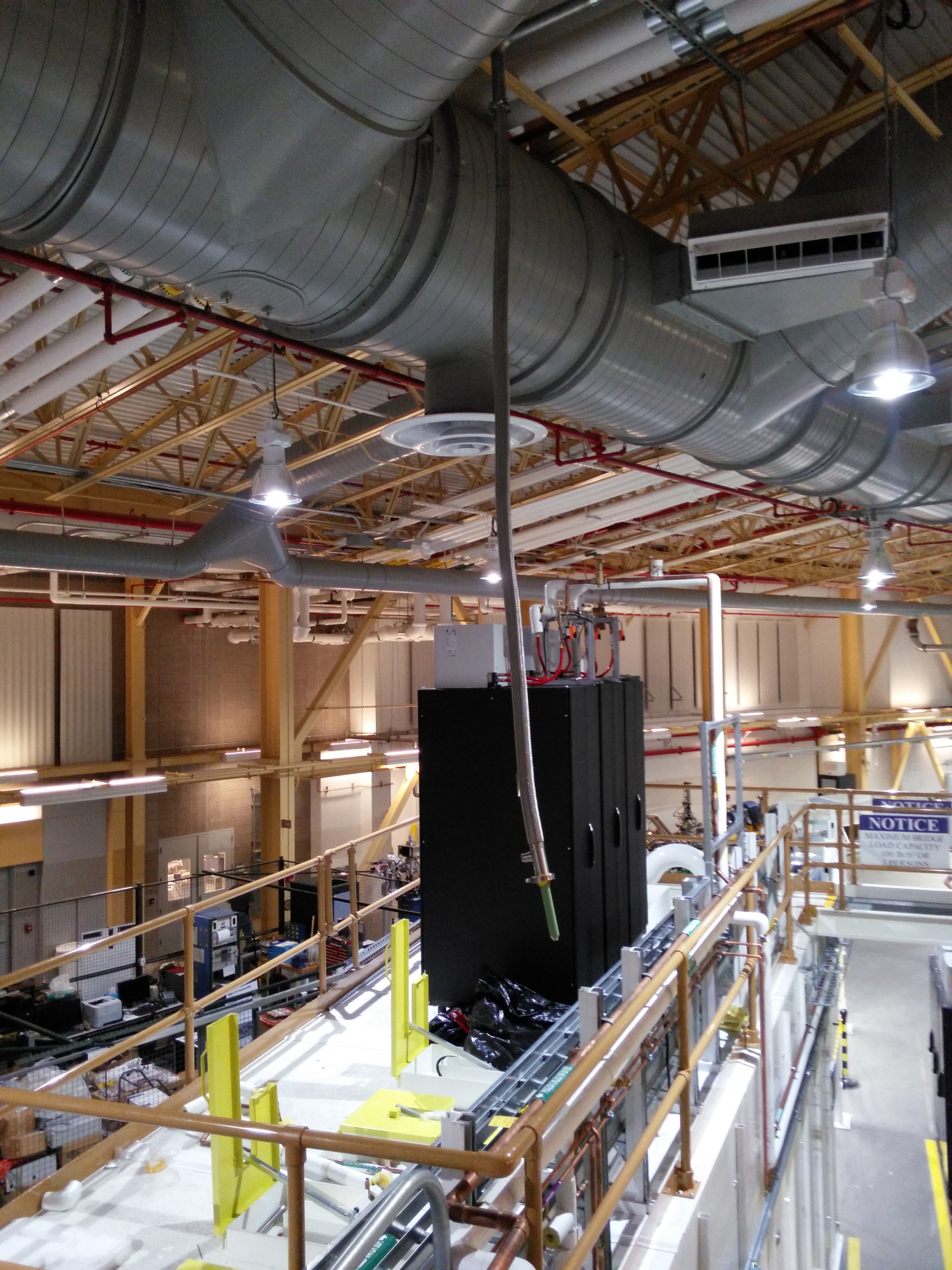
November 15, 2016
Ventilation was installed to the end station.
| View of ventilation from 7ID | Connection to hutch roof | Flyway to main exhaust system |
 |
 |
 |
November 8, 2016
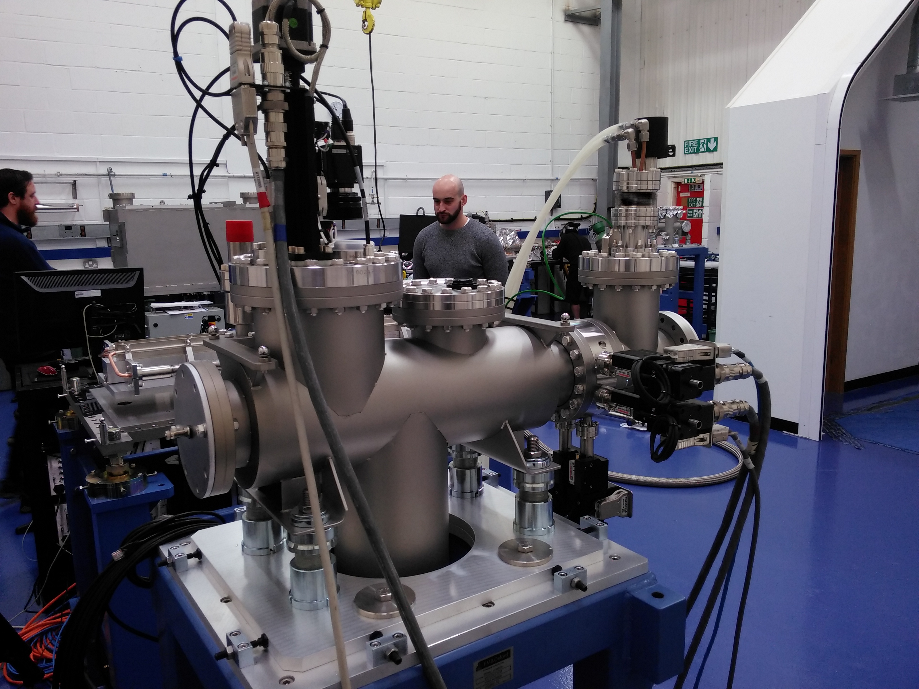
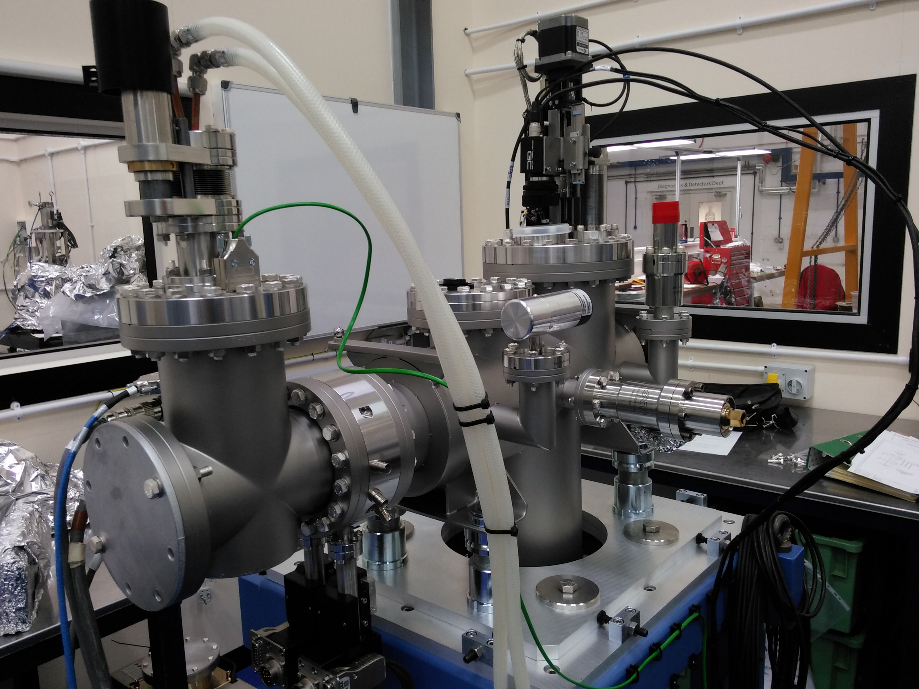
Factory acceptance testing at the FMB Oxford factory!
BMM Mirror 1
| M1 viewed from the perspective of the beam | View of the cooling slot in the dummy optic | Setting up for motion testing | Upstream vertical jack | Upstream horizontal translation | Downstream vertical jacks | Lead shielding for encoders |
 |
 |
 |
 |
 |
 |
 |
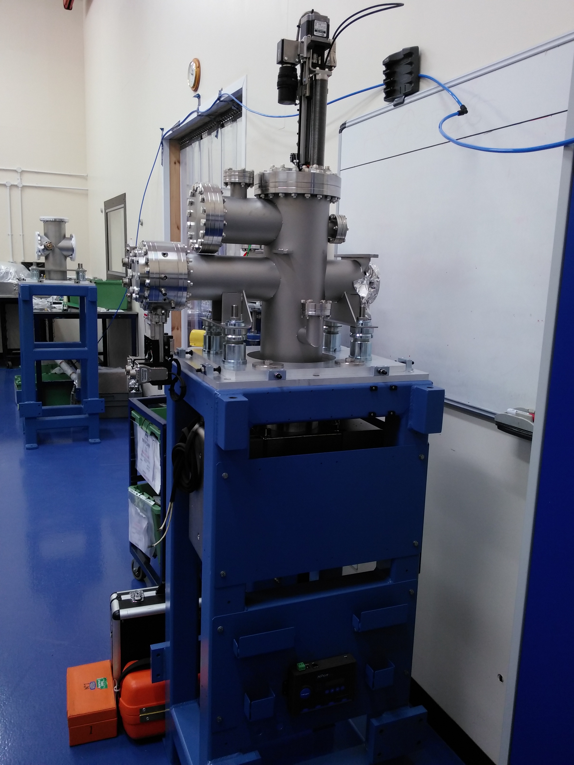
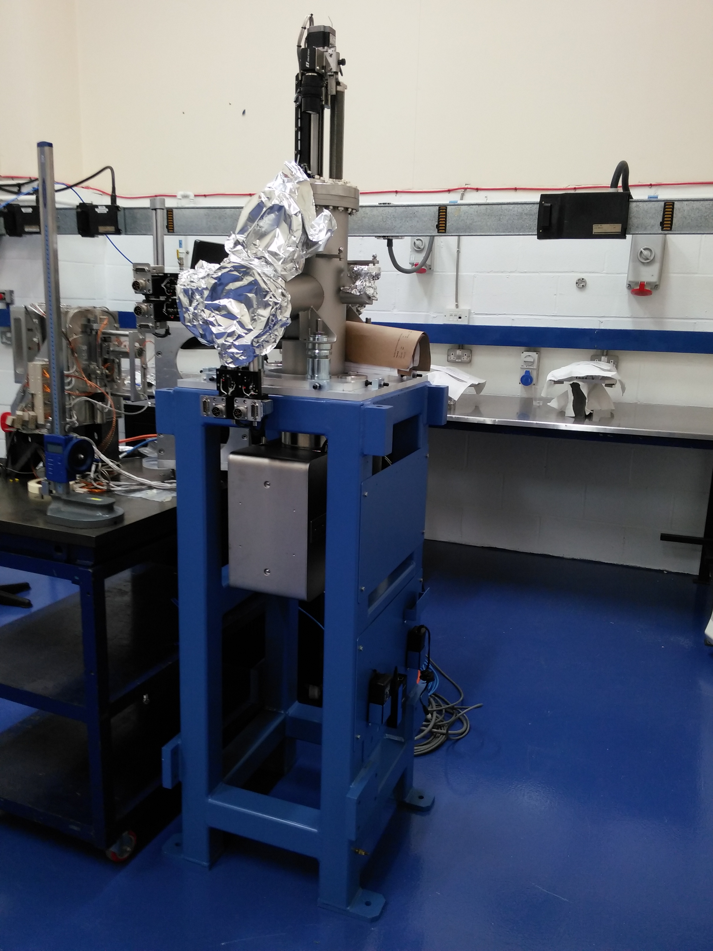
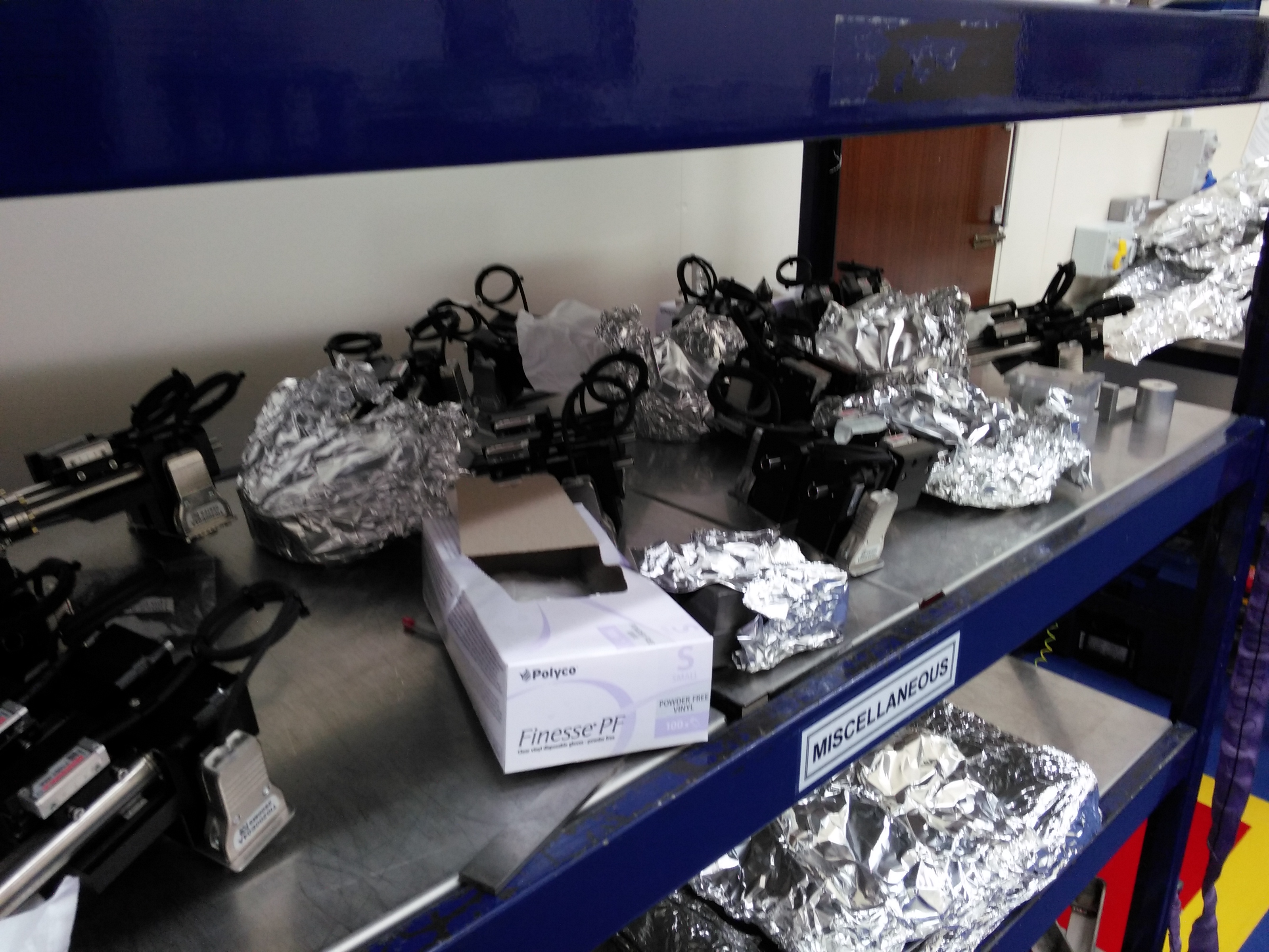
SST Diagnostic Modules
DM1 is ready to ship. Current from the photo diode in M1 was demonstrated while I was there. DM3 is complete and ready for bake-out. DM7 needs alignment before bake.
| DM1 | DM1 | DM3 | DM7 | unassembled diagnostic modules |
 |
 |
 |
 |
 |
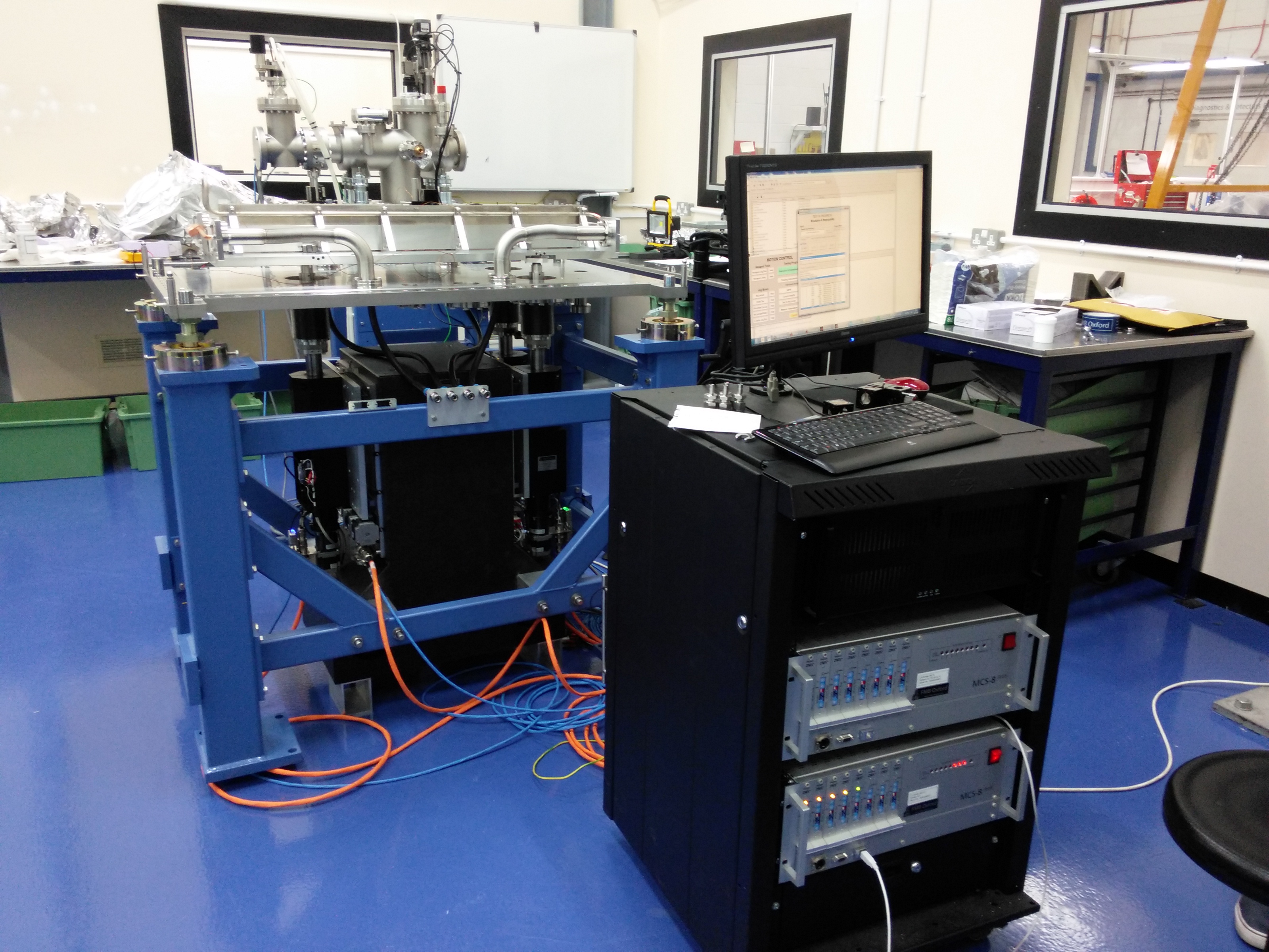
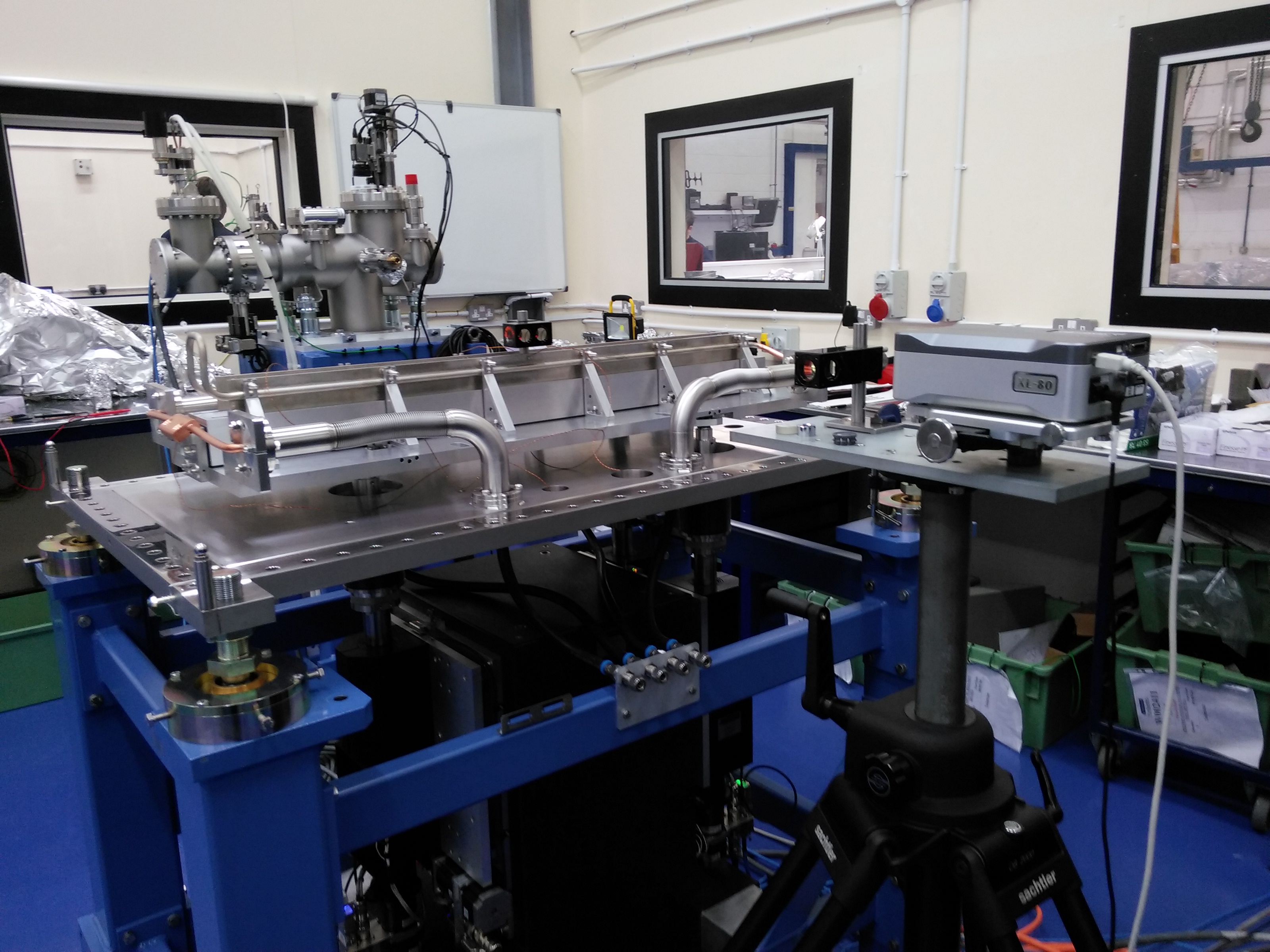
BMM M1 testing demonstration
| M1 pitch measurement | M1 pitch test + test computer | M1 Yaw measurement |
 |
 |
 |
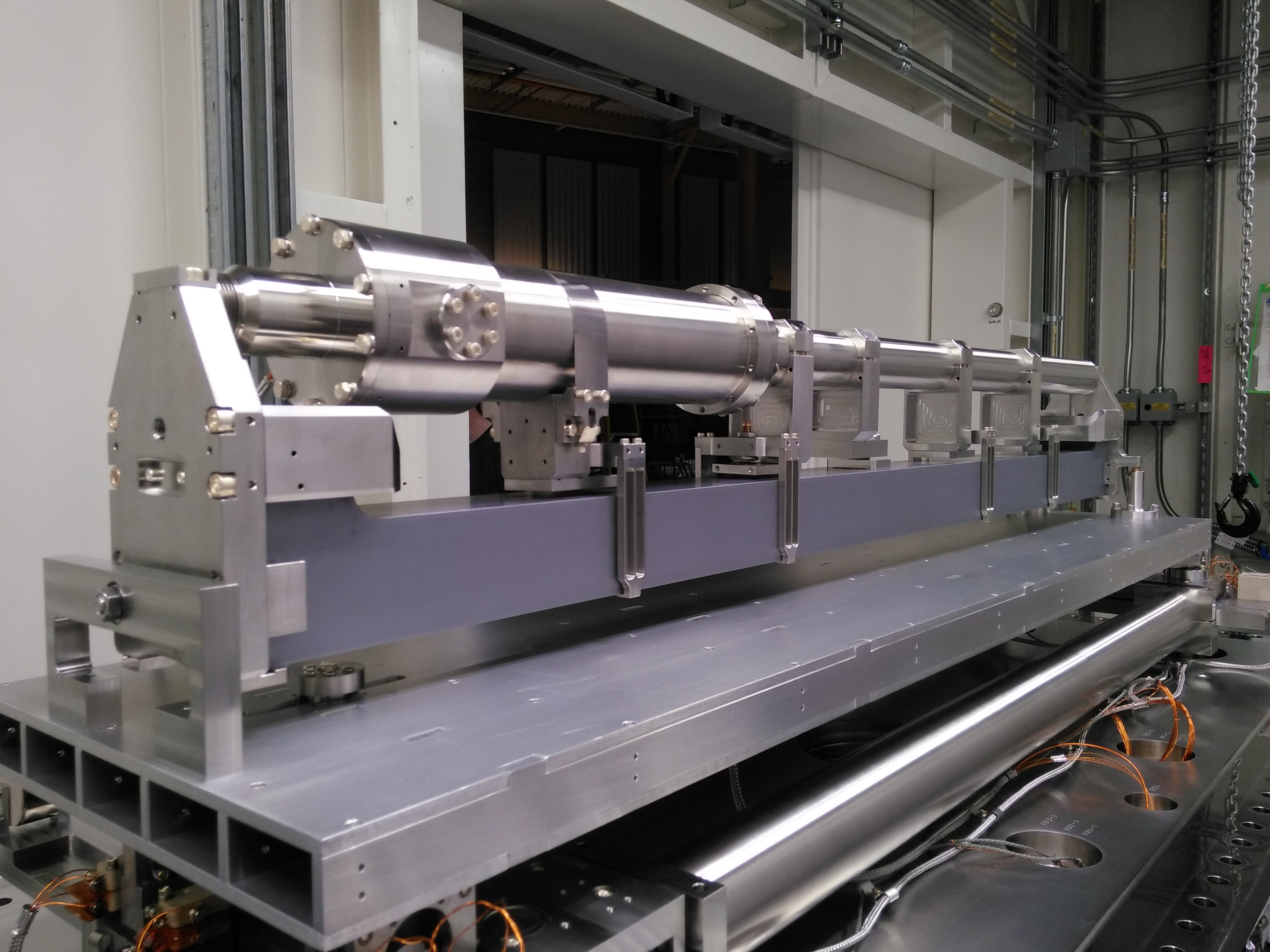
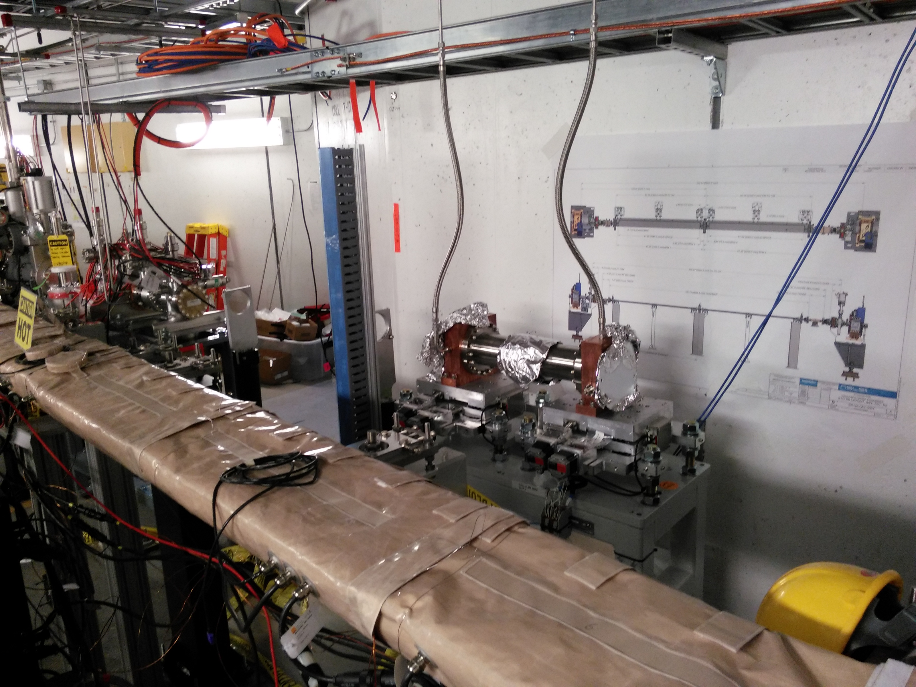
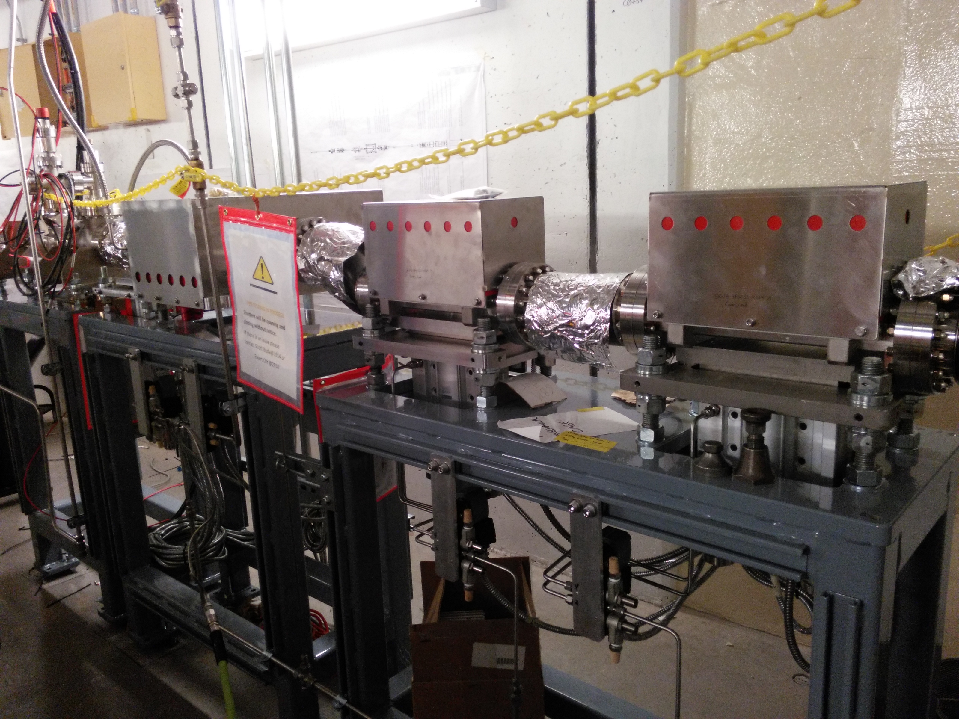
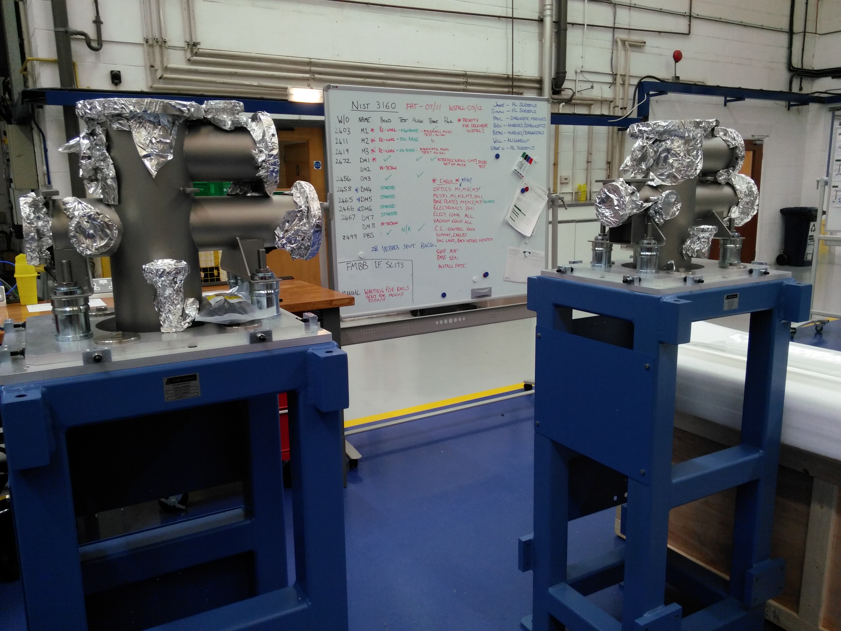
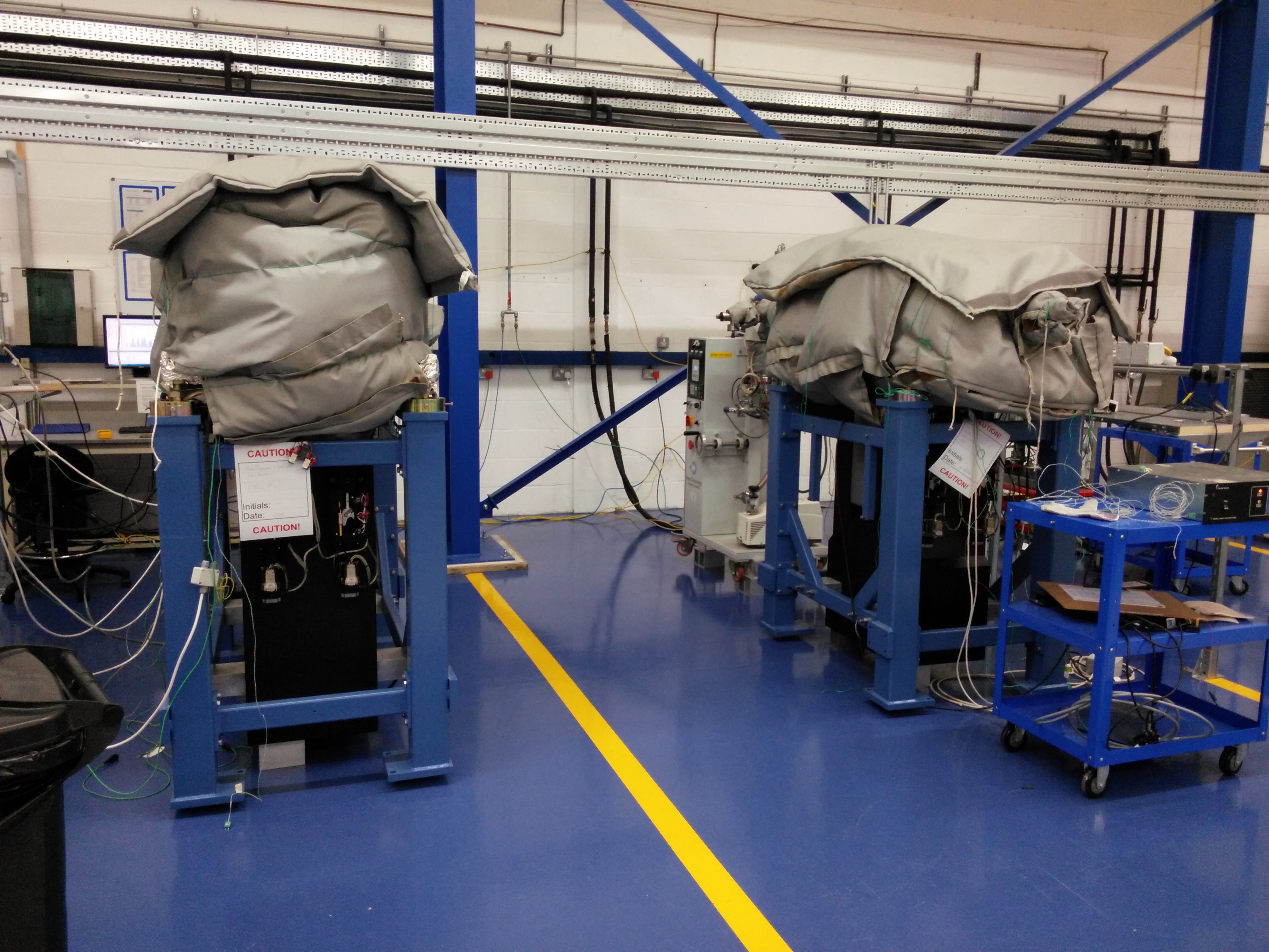
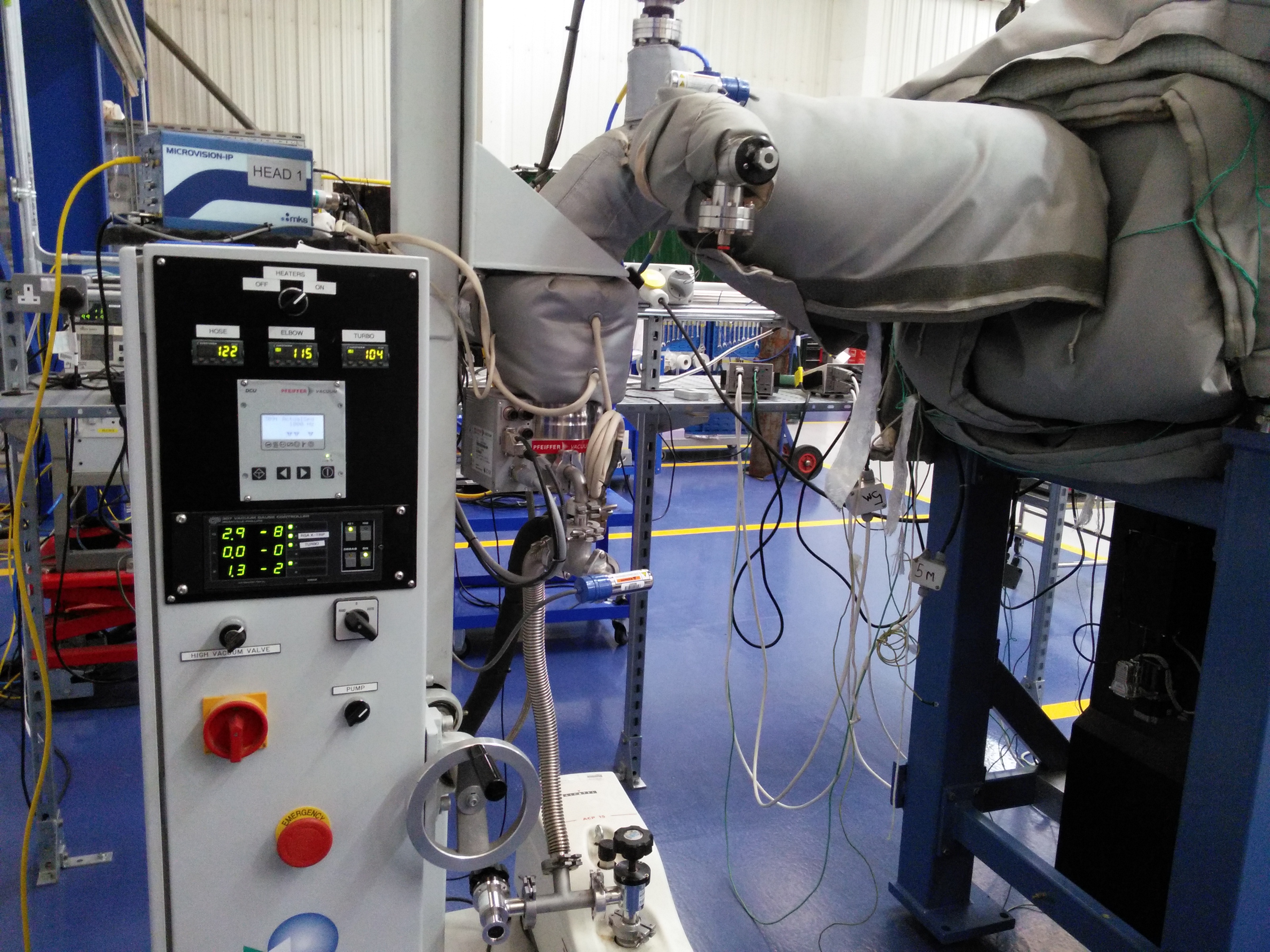
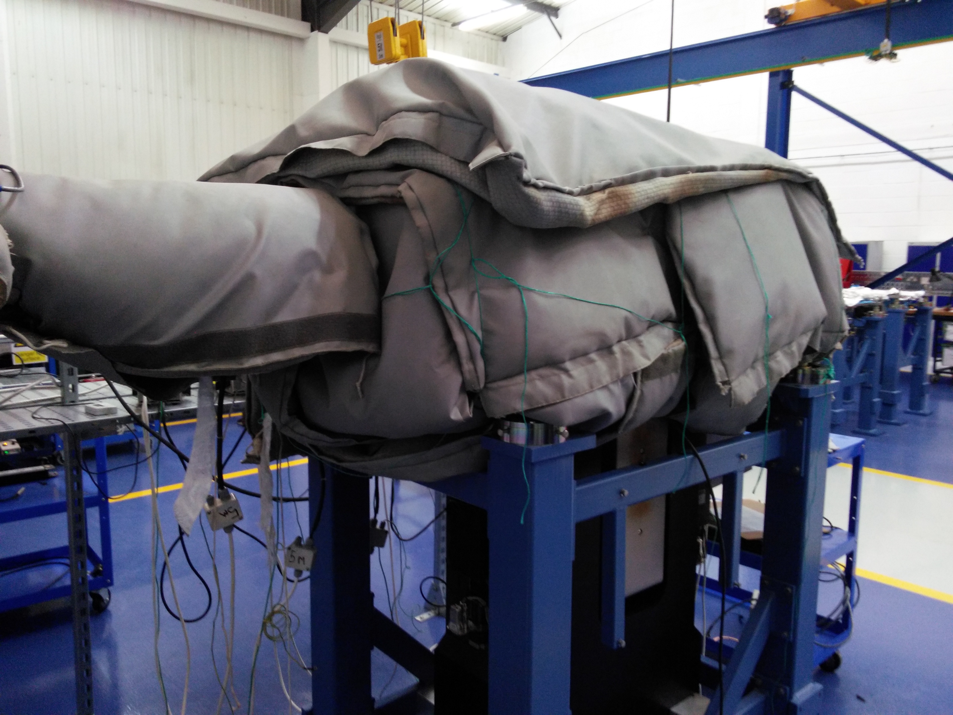
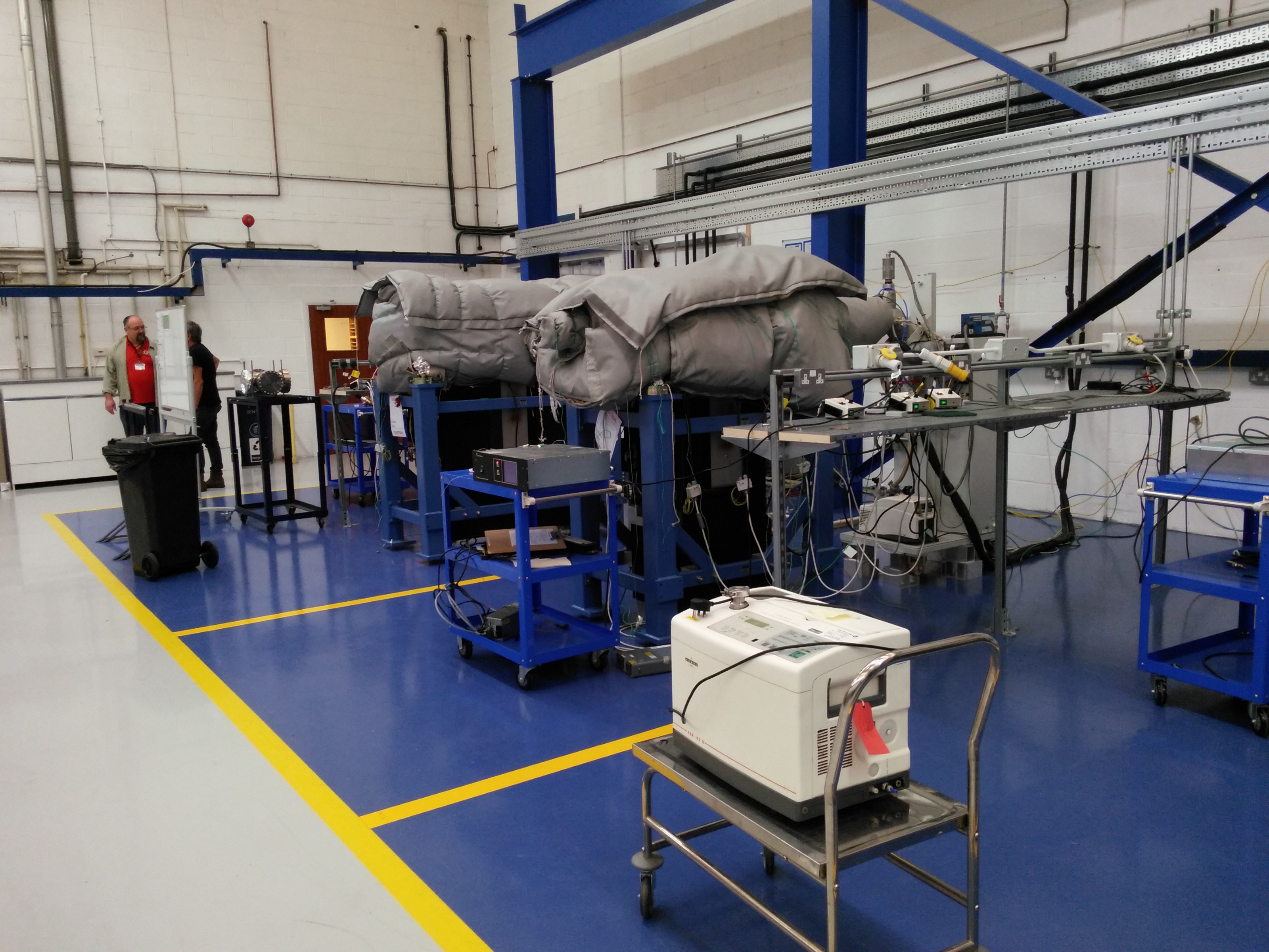
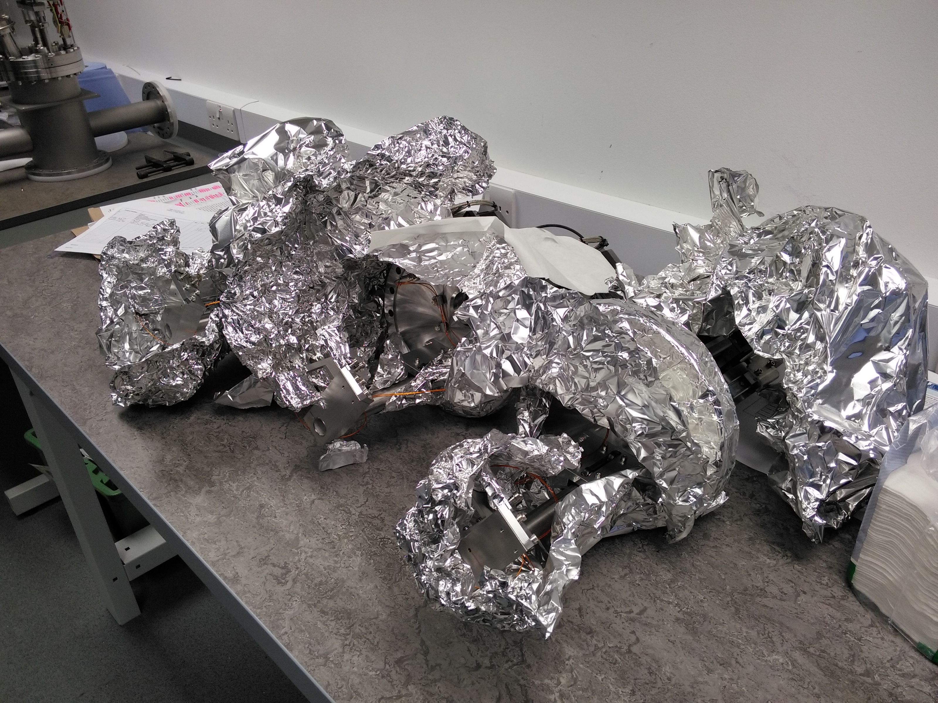
BMM M2 and M3 bake-out
| M2 and M3 at their bake-out stations | Bake-out rig | Blanketed mirror | another view |
 |
 |
 |
 |
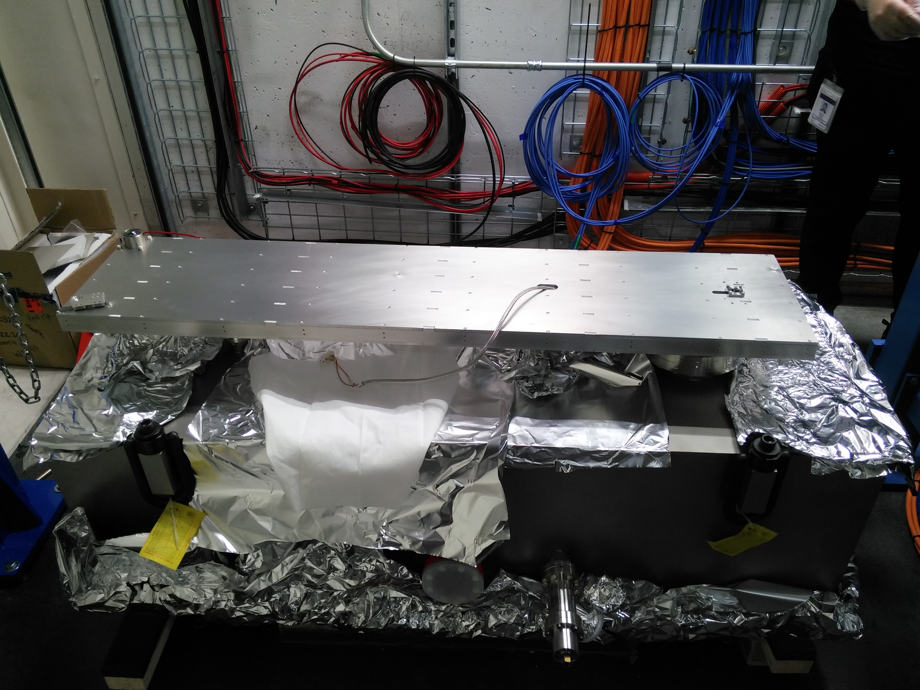
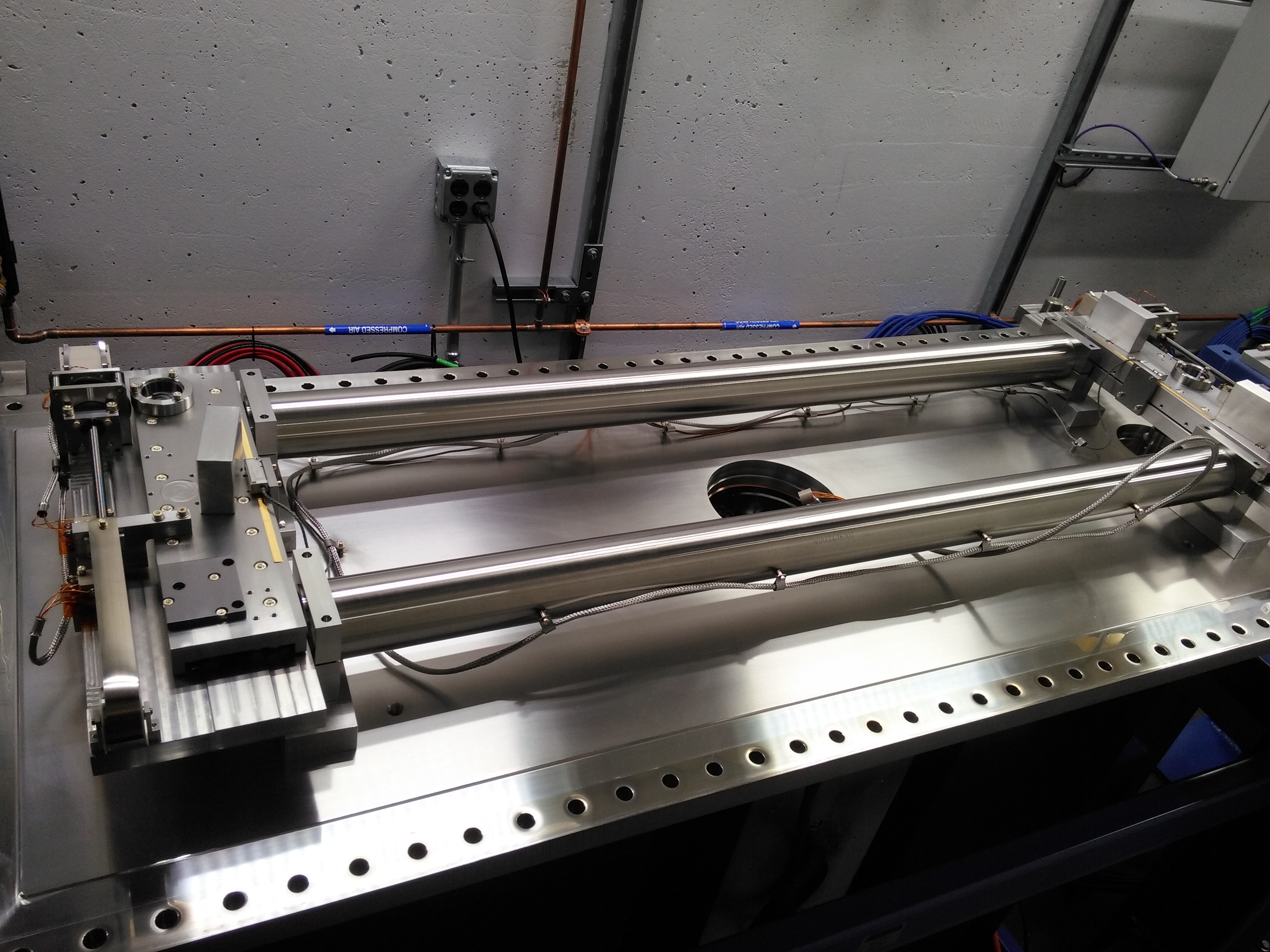
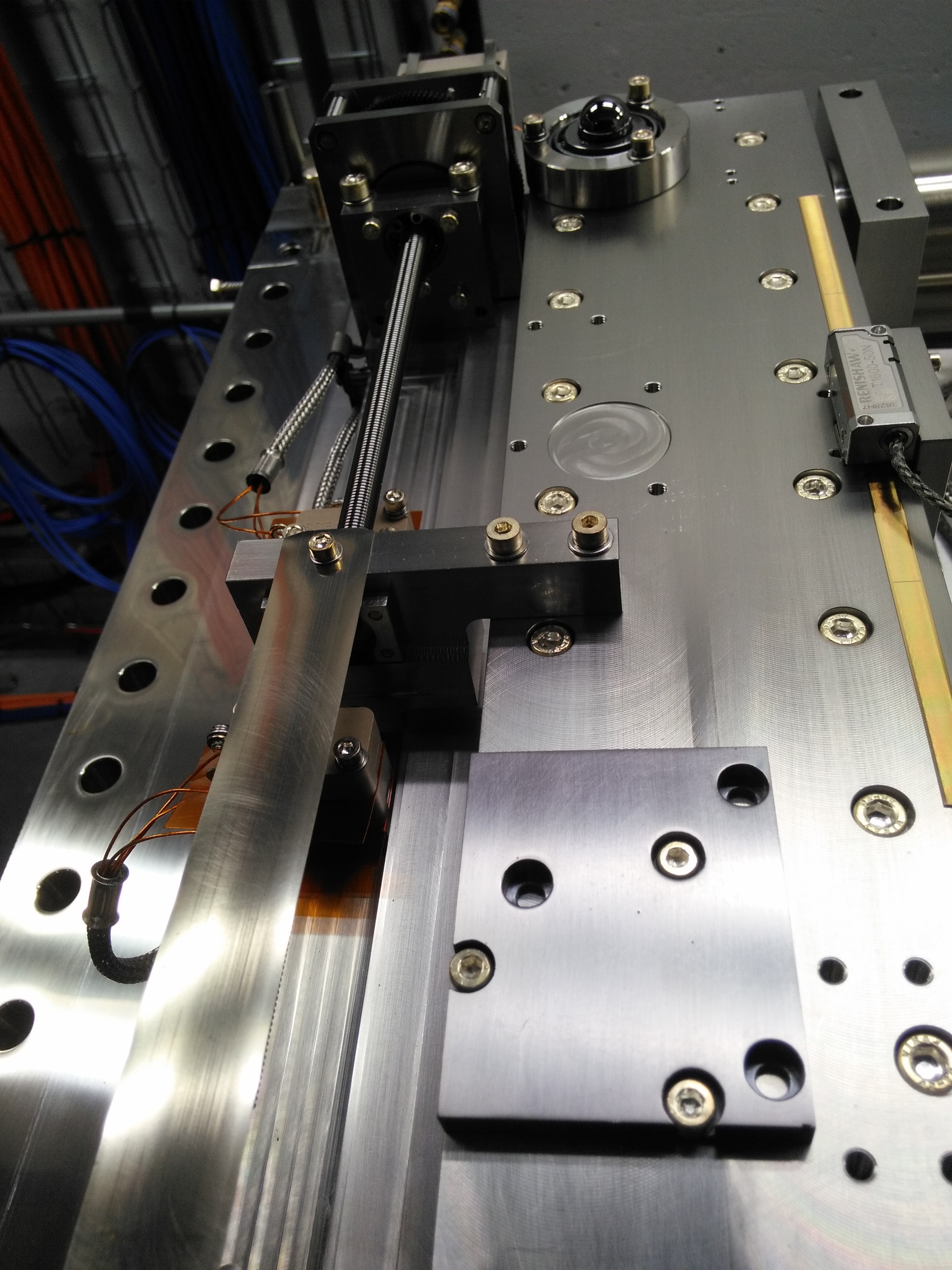
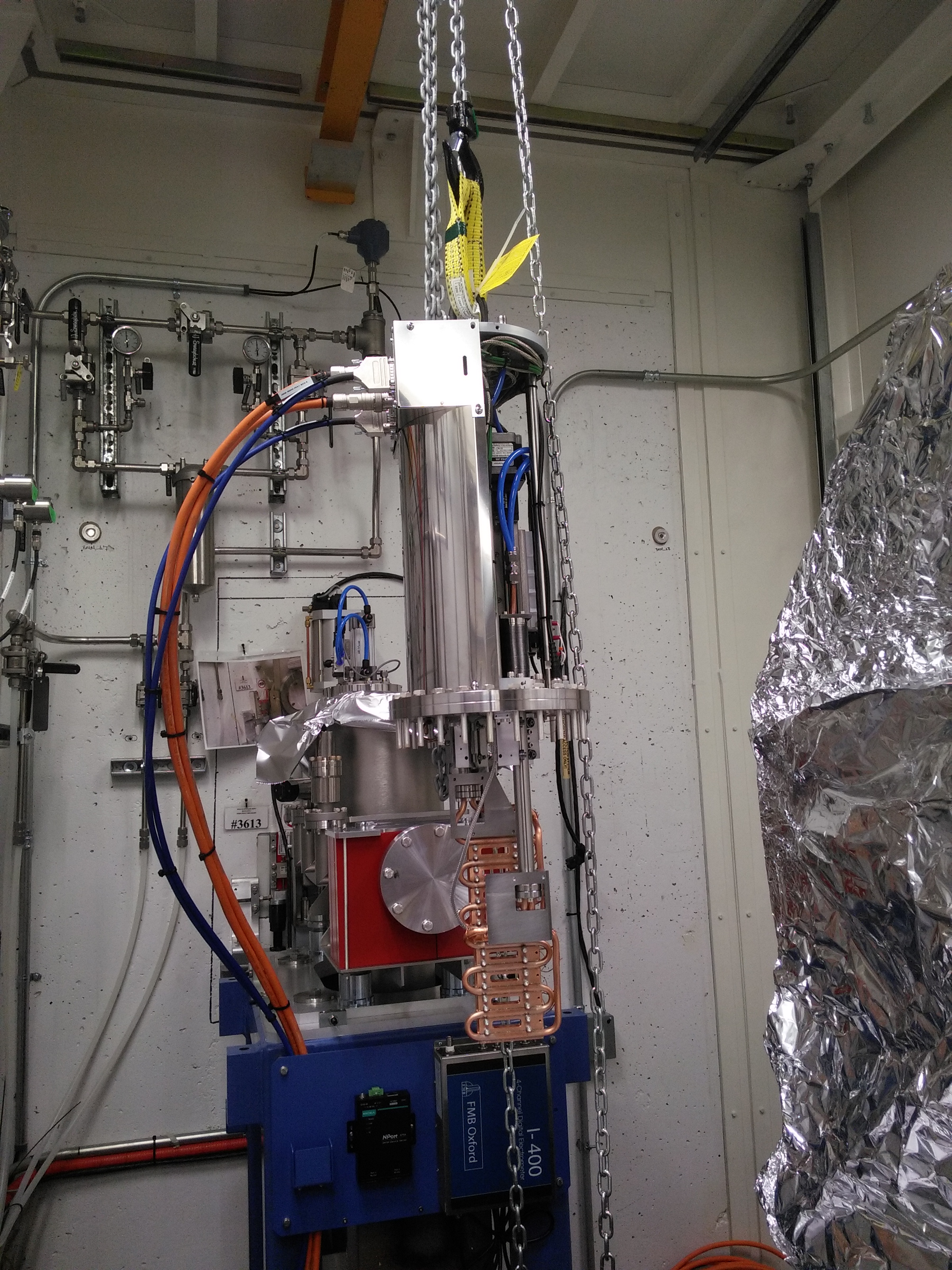
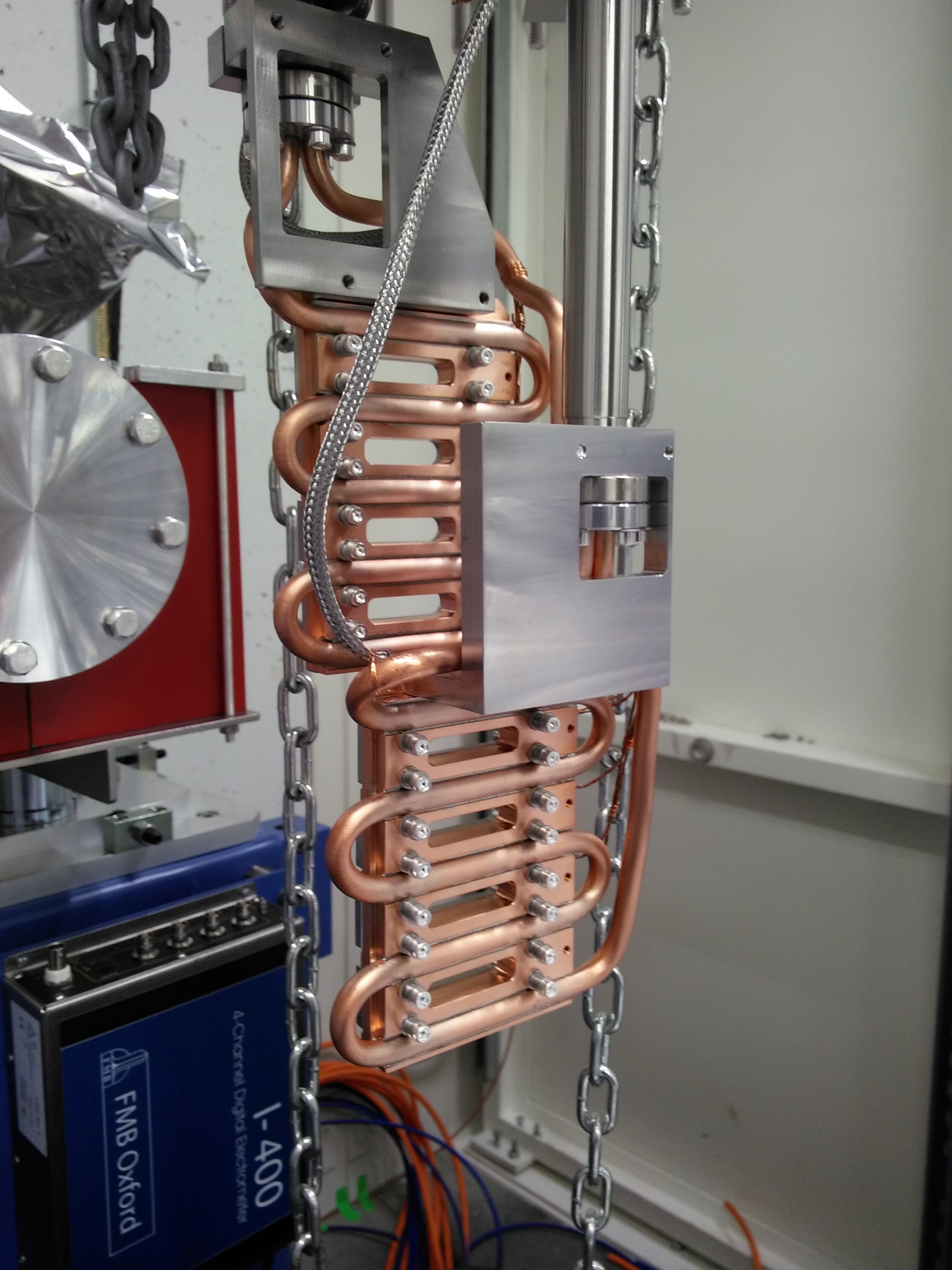
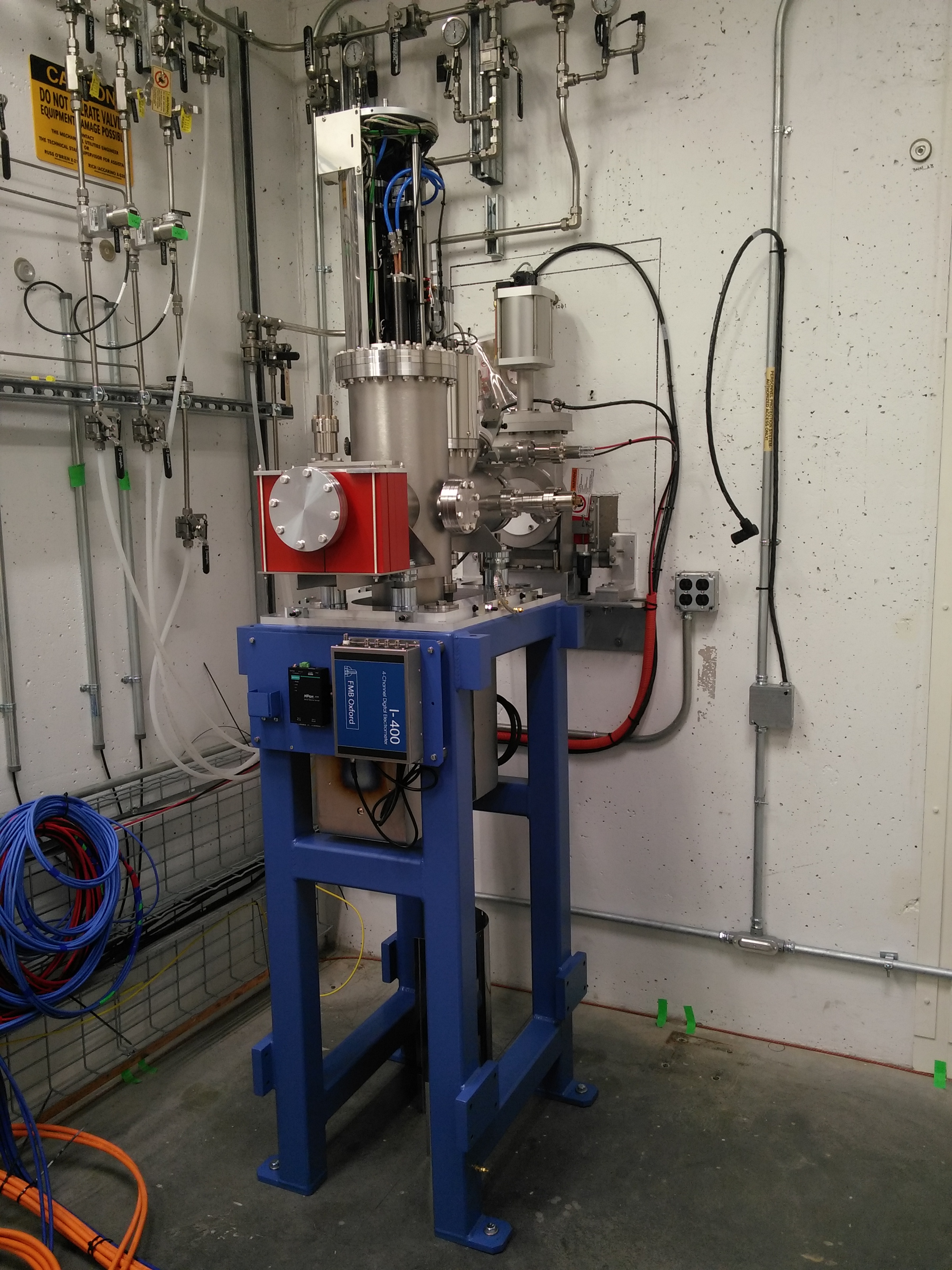
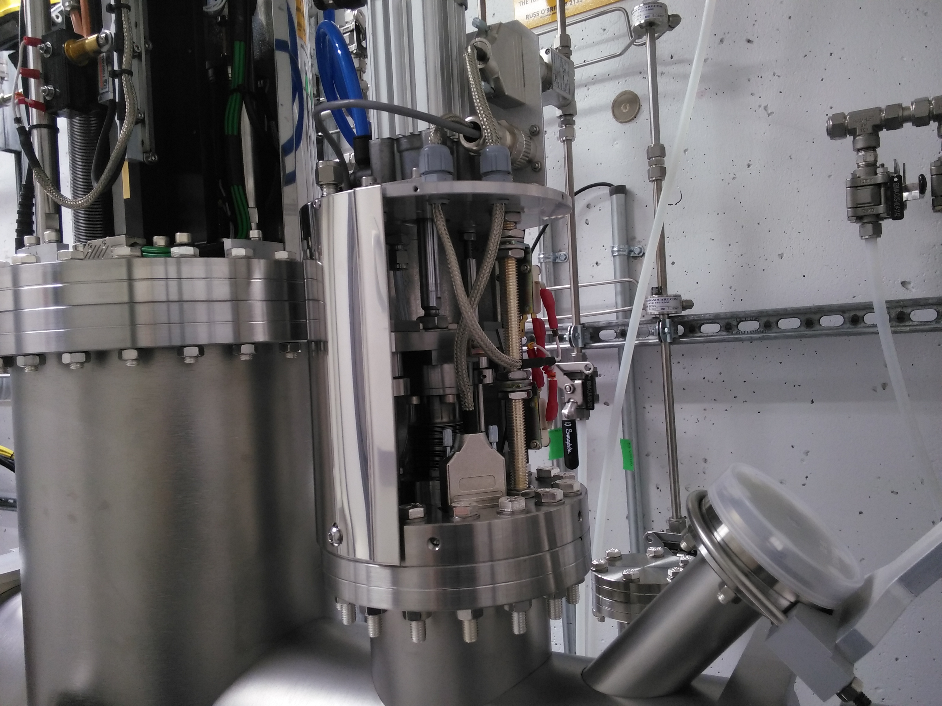
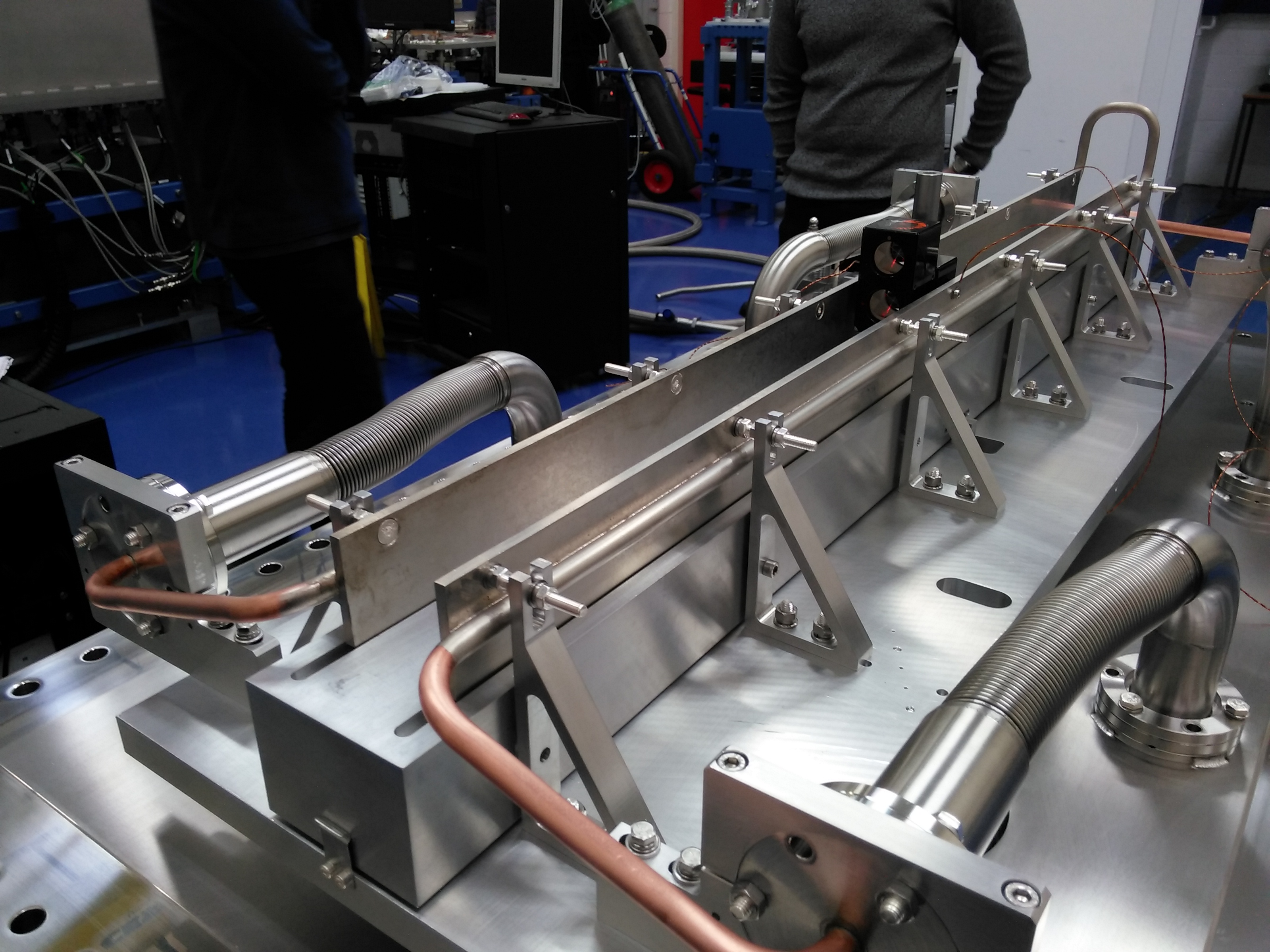
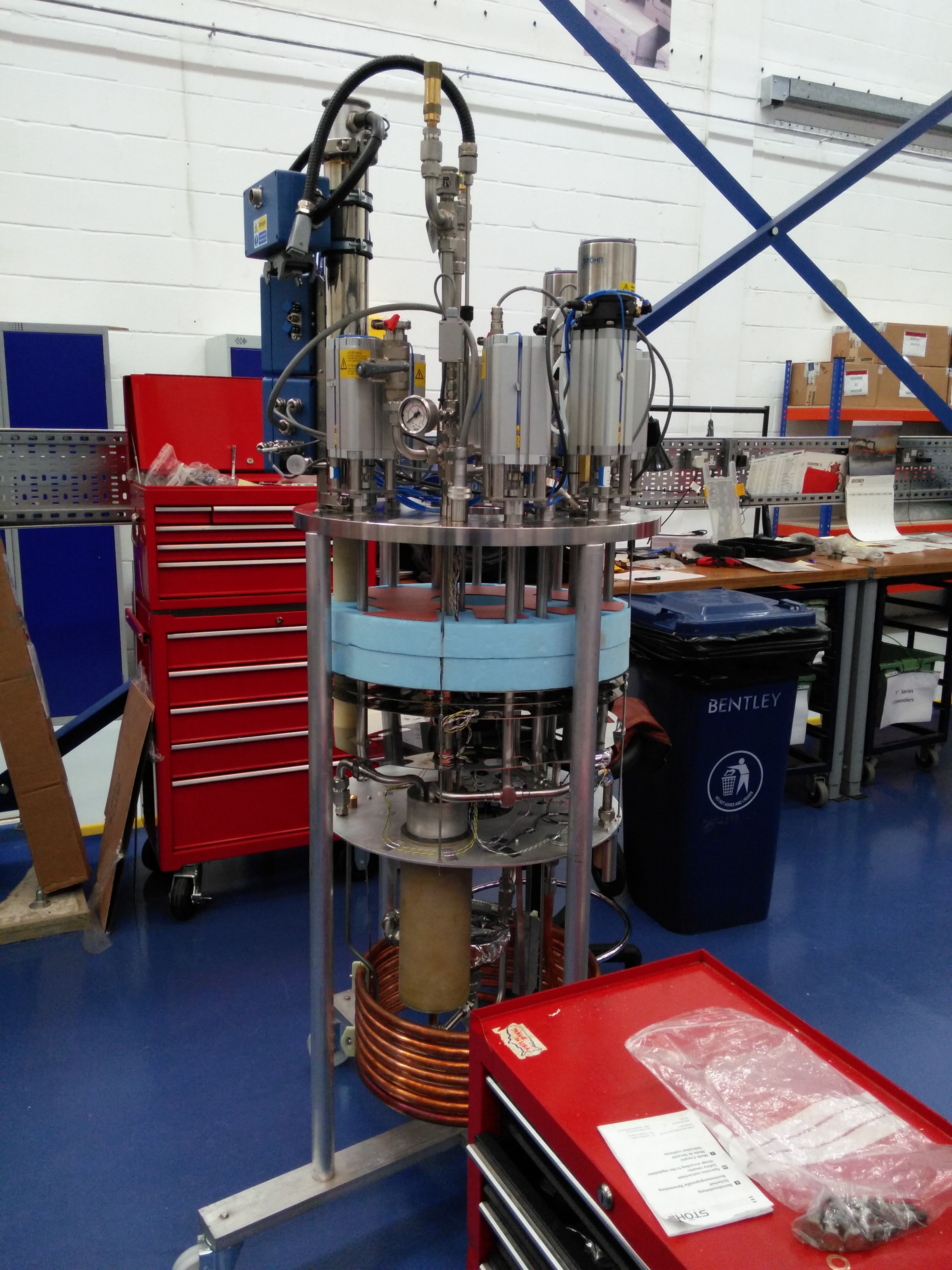
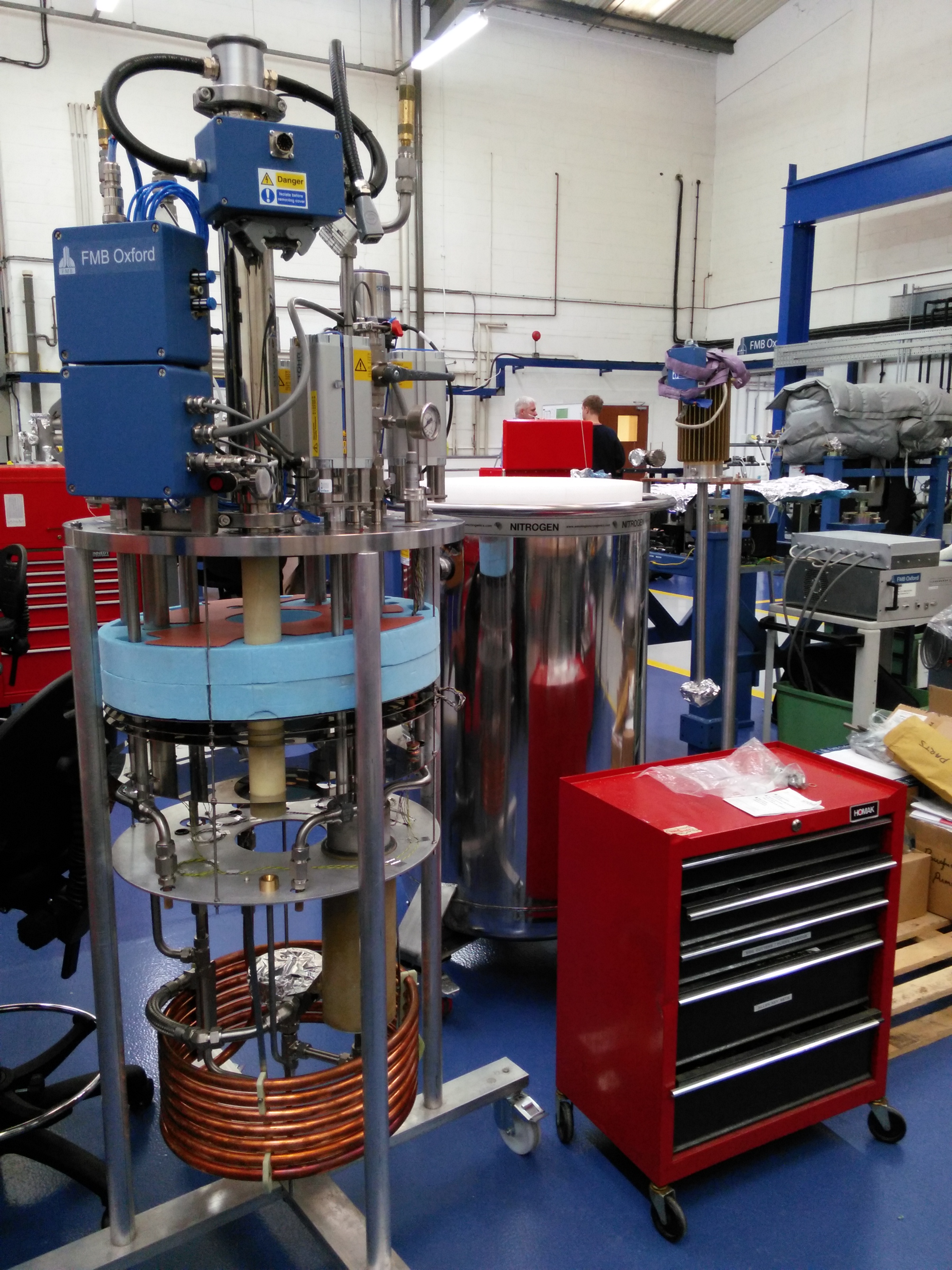
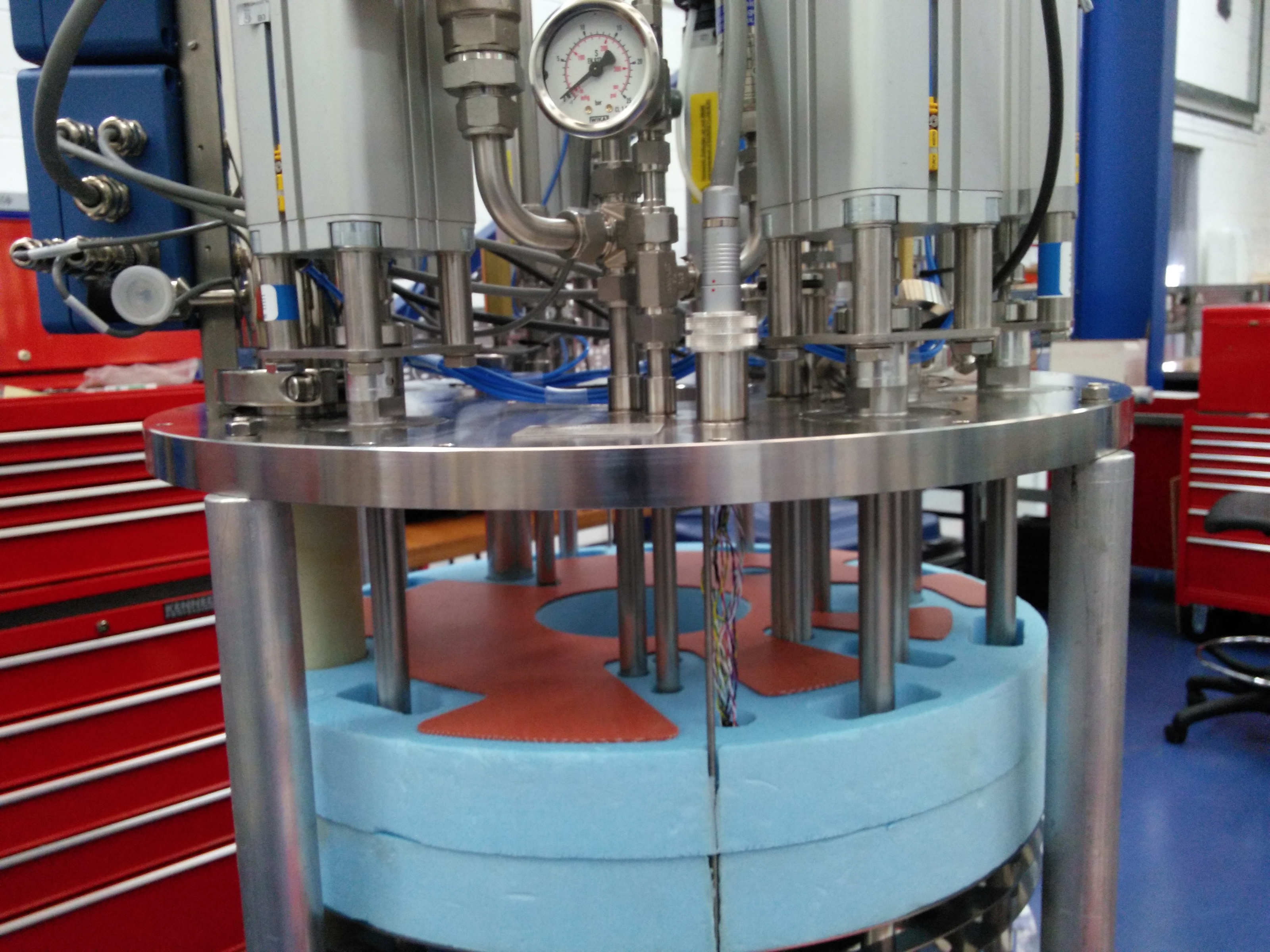
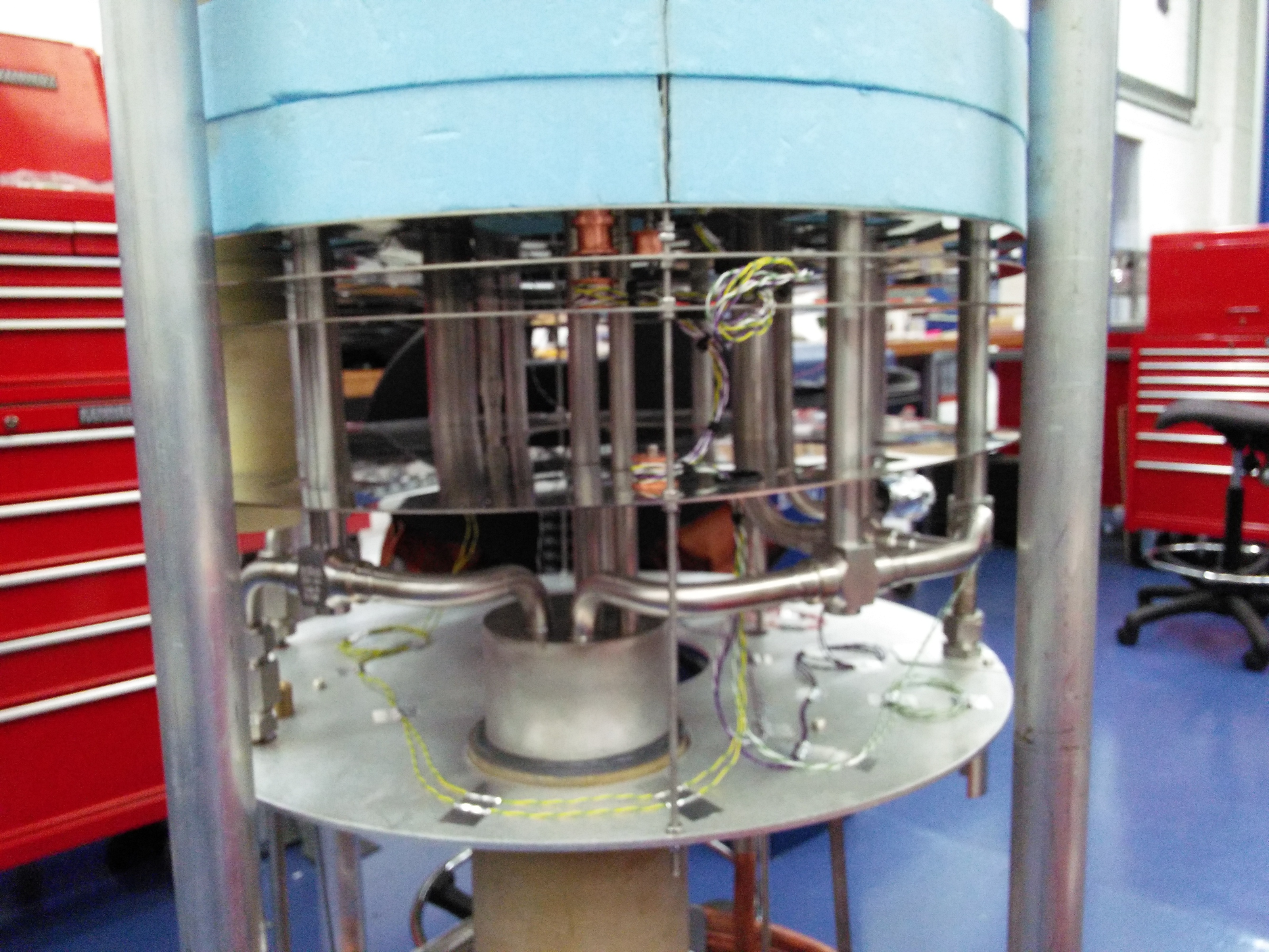
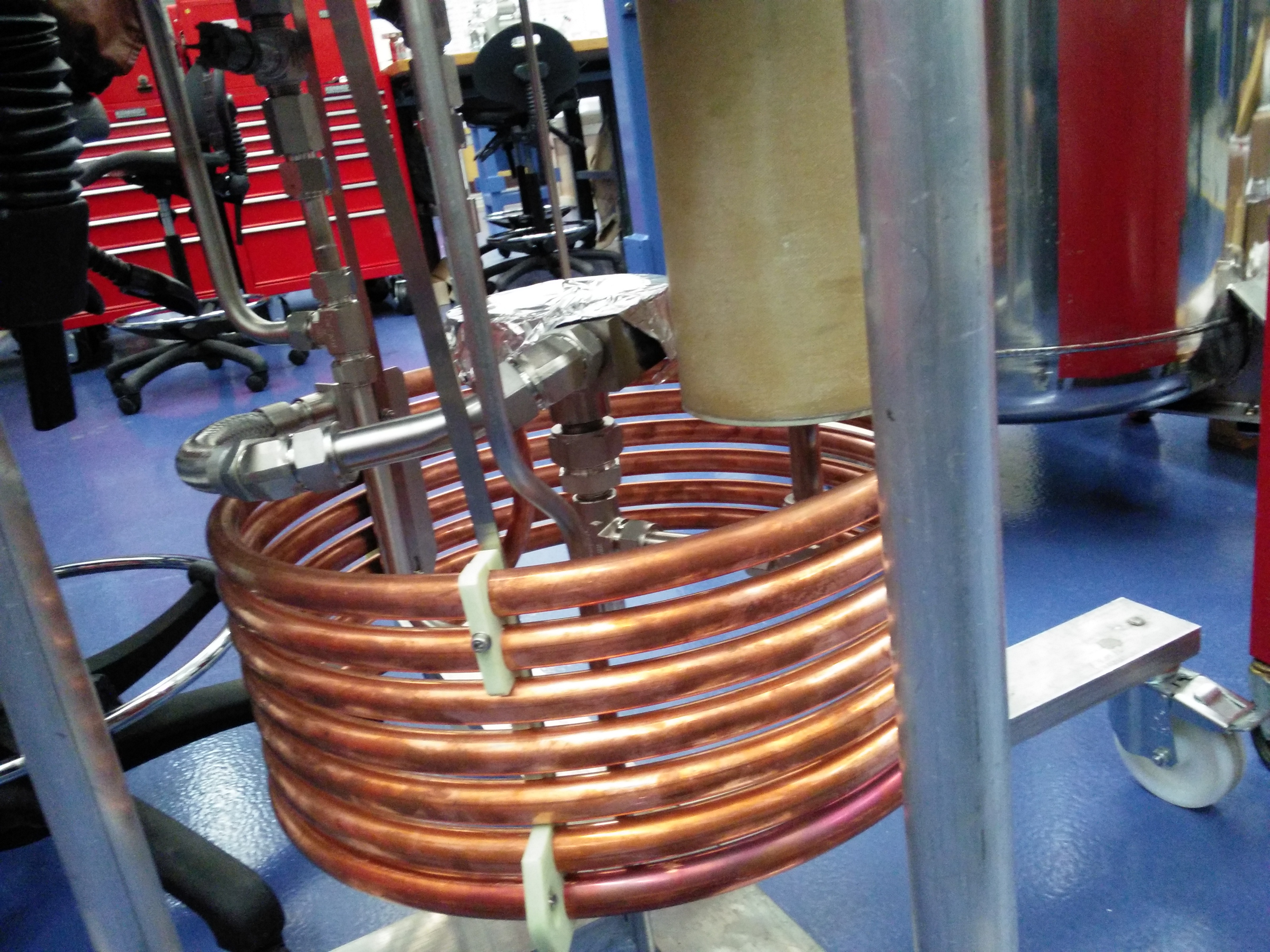
SST cryocooler
| Cryocooler at its build station | Cryocooler and its housing | closeup | closeup | closeup |
 |
 |
 |
 |
 |
Slits and diagnostics in various states of assembly
 |
 |
 |
 |
 |
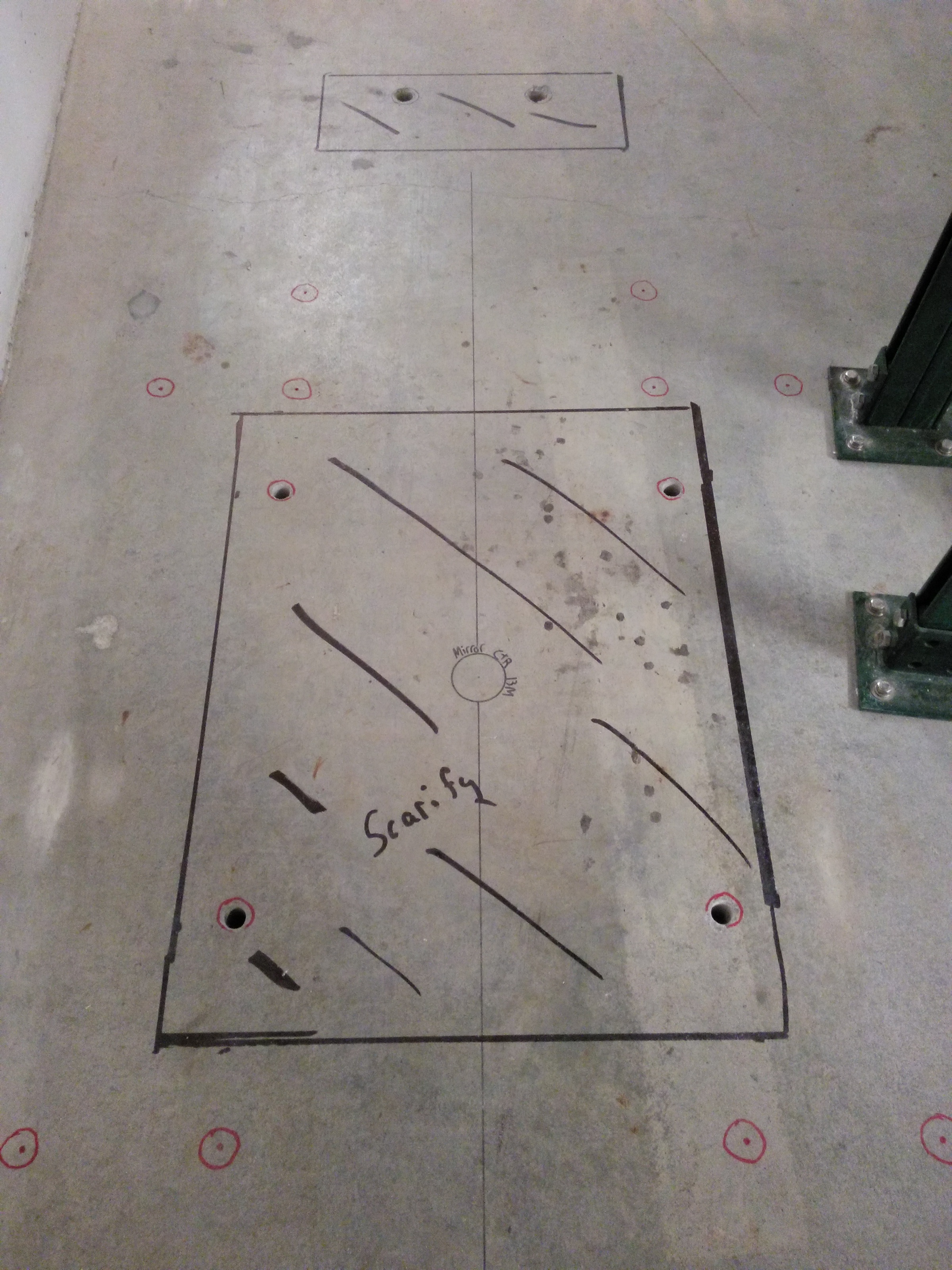
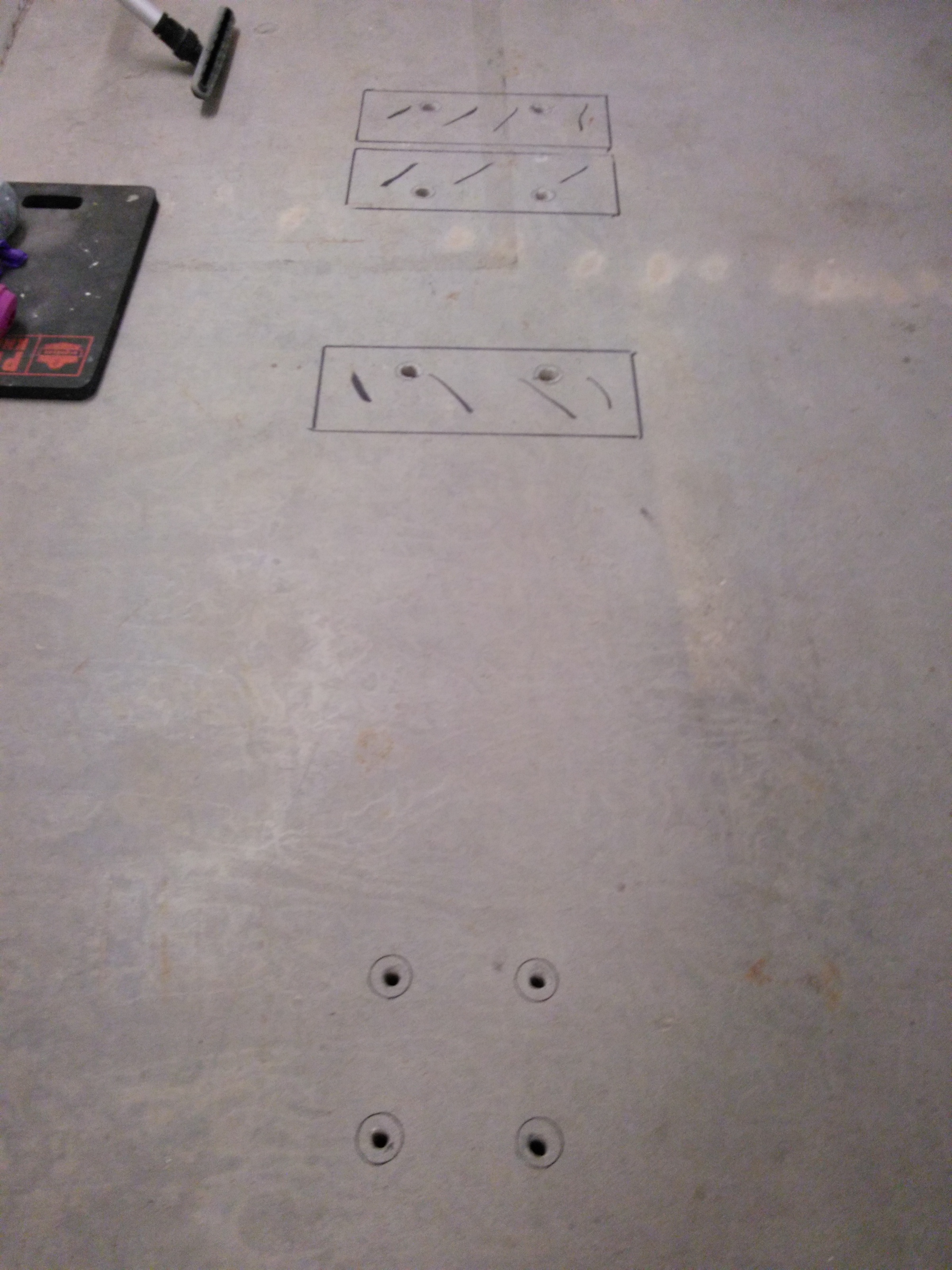
October 18, 2016
Front end floor drilling started today.
| M1 location | Shutter location near the ratchet wall |
 |
 |
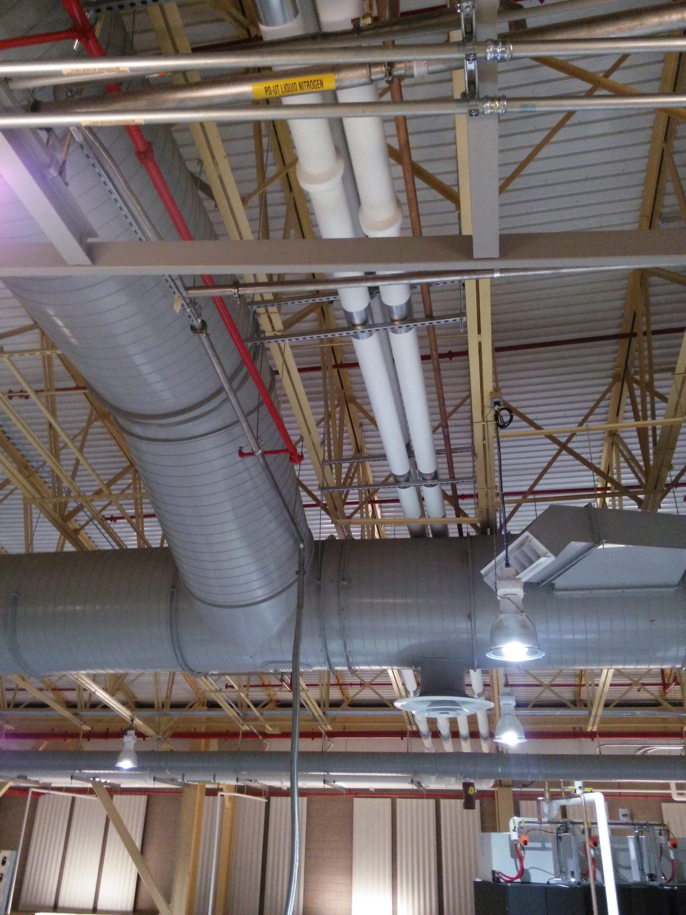
October 6, 2016
Liquid nitrogen distribution is installed!
| Drop point on 6BM-A roof | LN2 line entering the labyrinth | LN2 tap in the end station |
 |
 |
 |
October 3, 2016
Liquid nitrogen distribution is being installed!
| LN2 line dropped through hutch labyrinth | Components of LN2 distribution system | LN2 feedline from roof | LN2 distribution to 6BM and 7ID | LN2 distribution from source |
 |
 |
 |
 |
 |
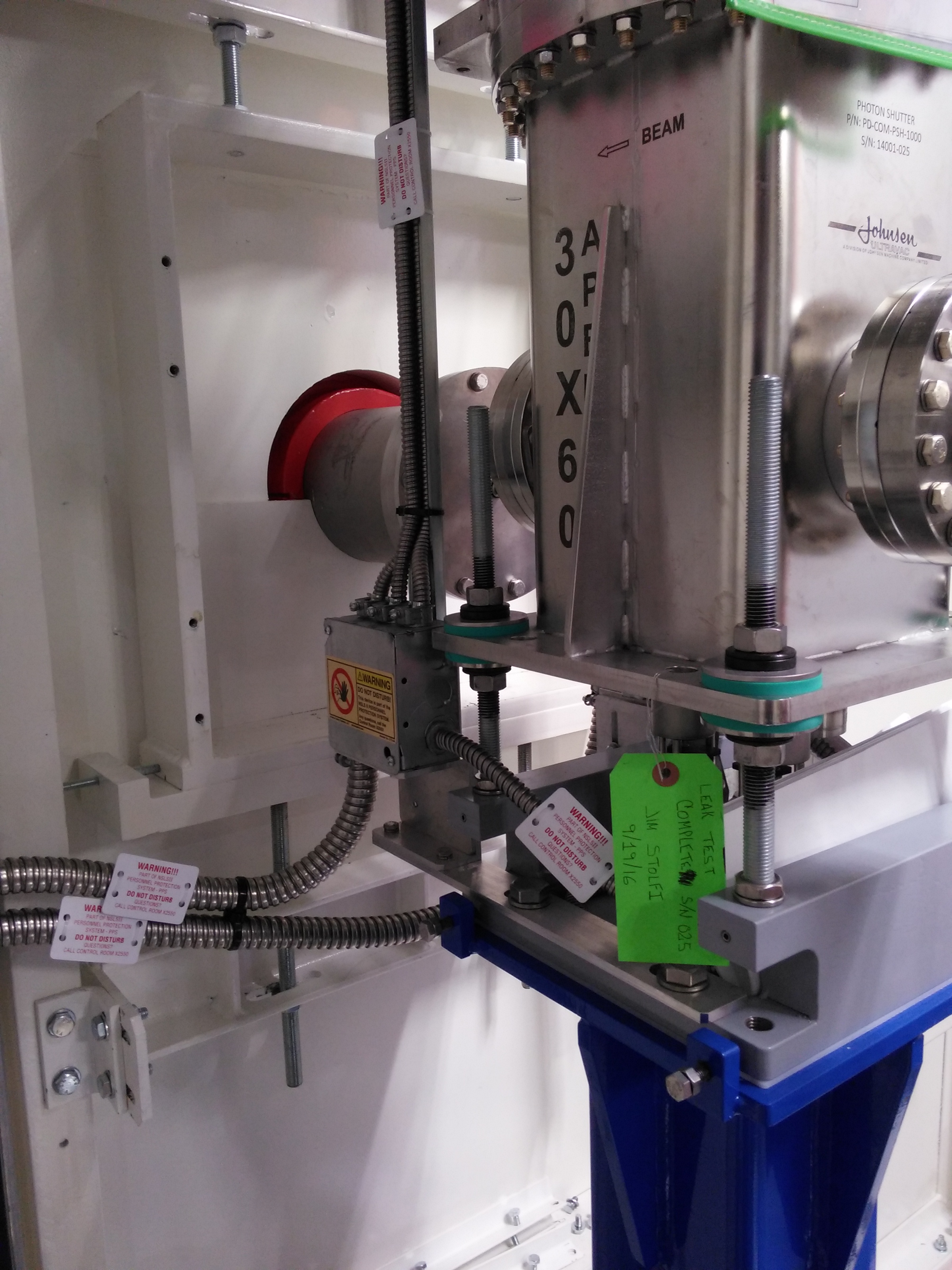
September 16, 2016
Figure 5: The 6BM user photon shutter arrived!
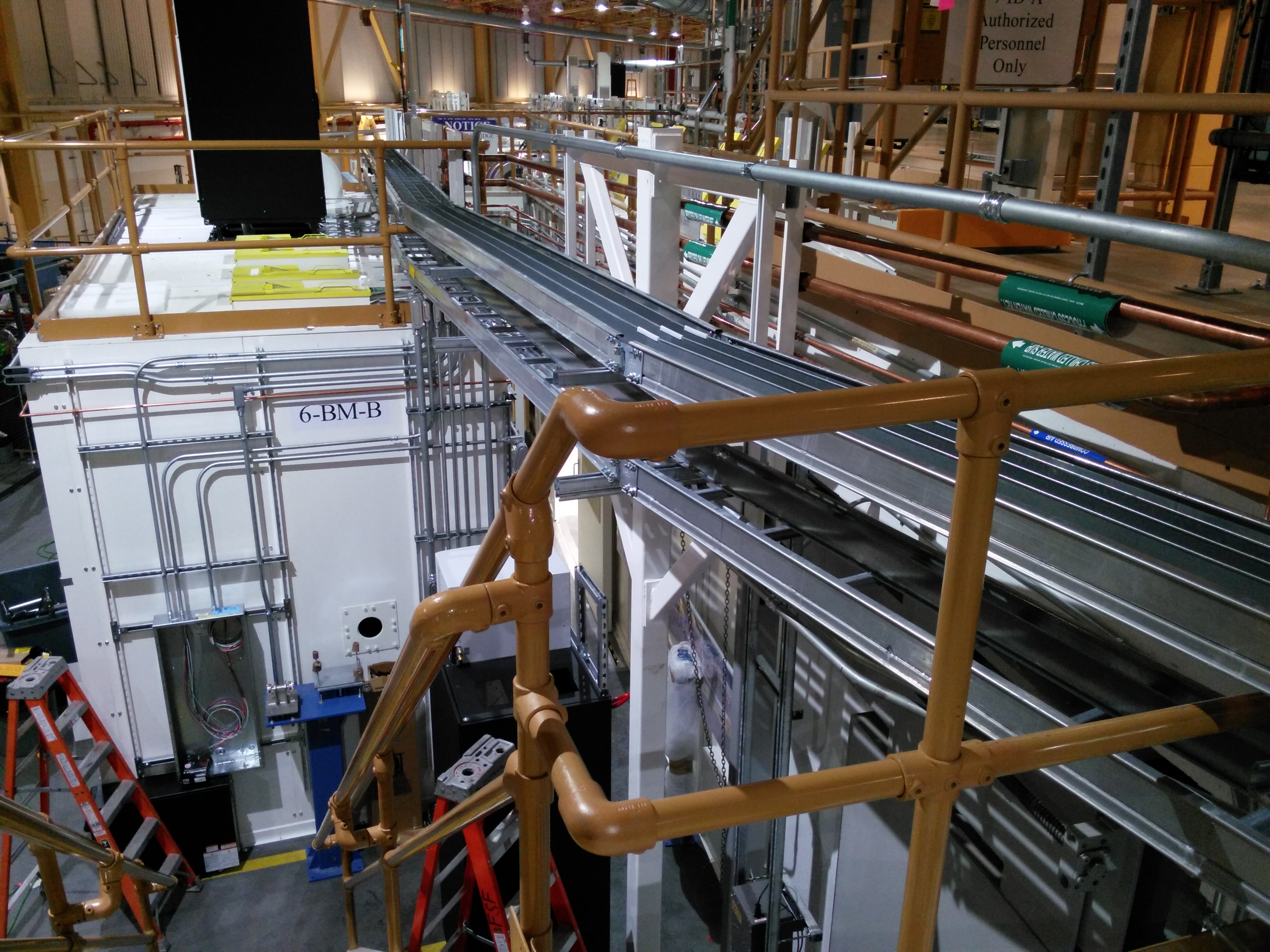
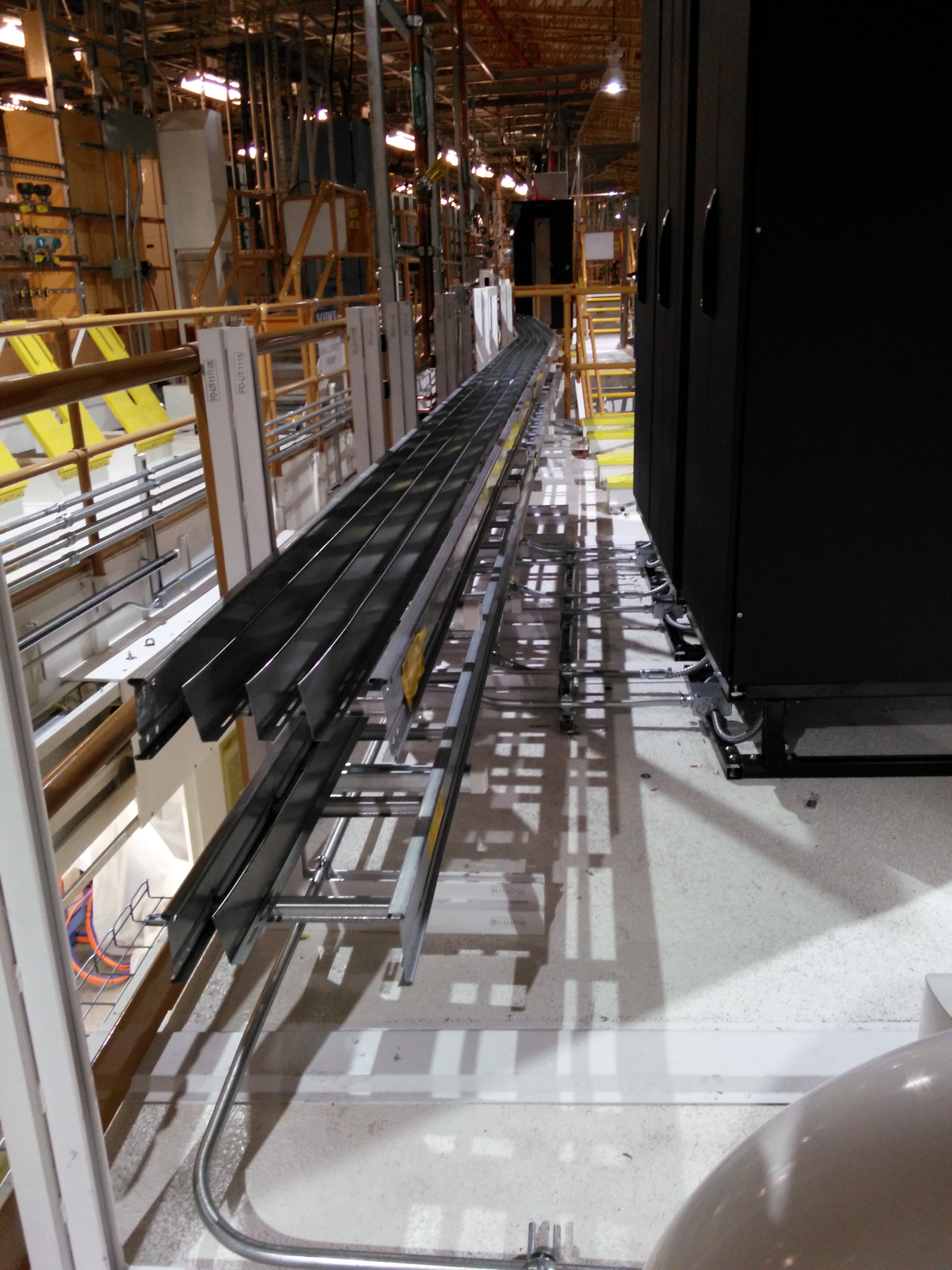
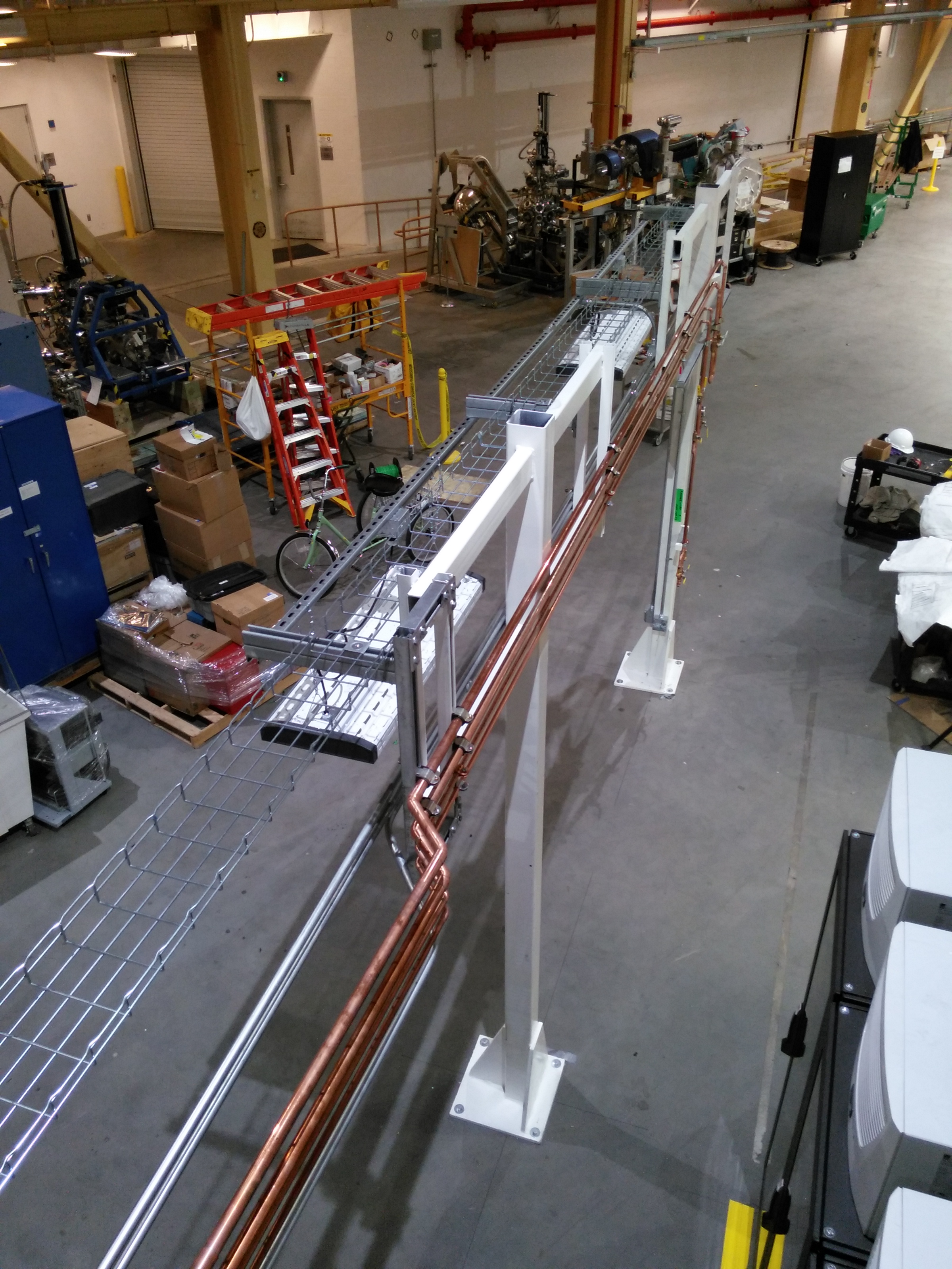
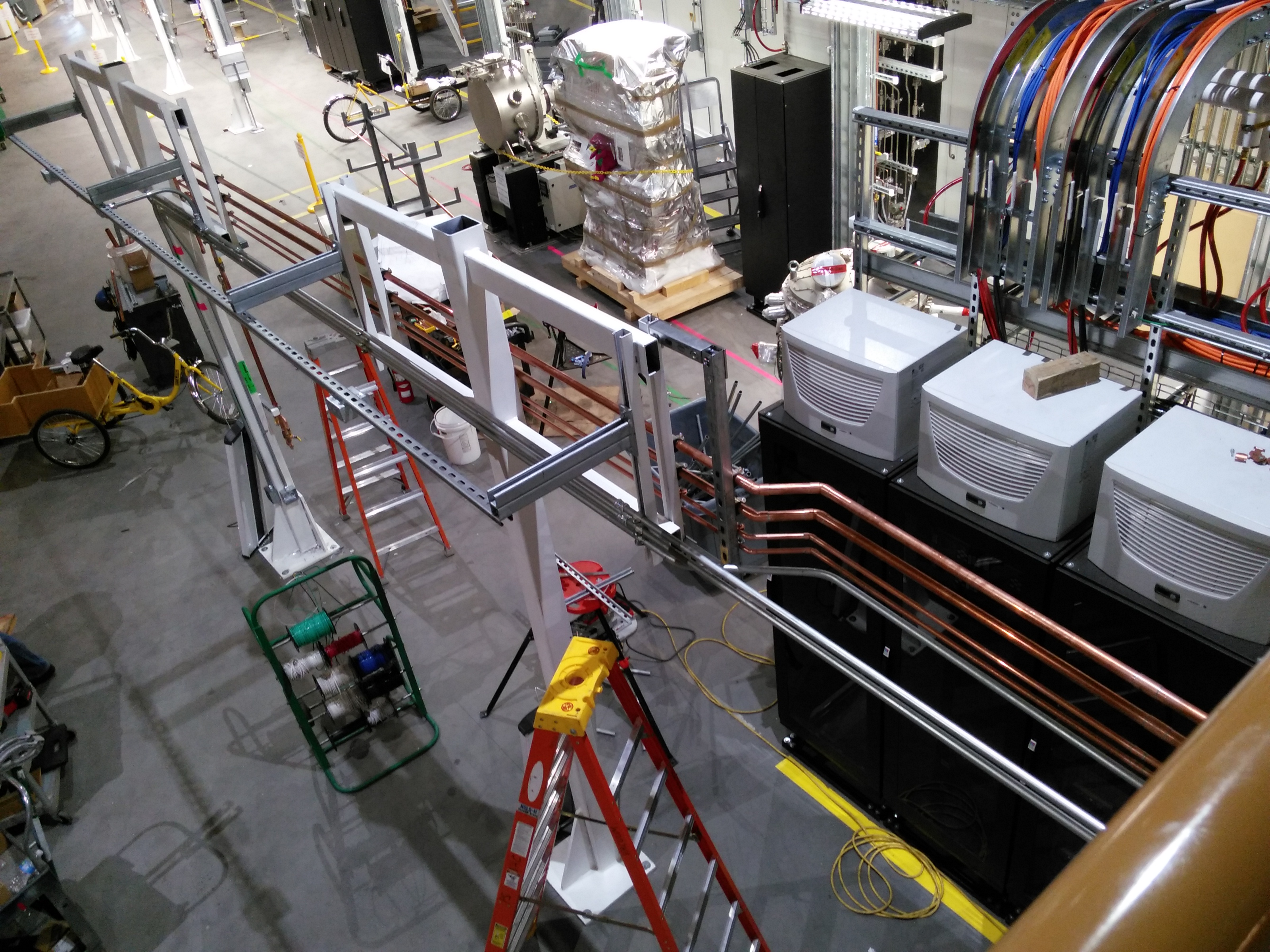
June 17, 2016
| Cable trays! | Cable trays, looking upstream | Power to the racks! | Water distribution on 6BM-B | Services from the mezzanine to 6BM-A |
 |
 |
 |
 |
 |
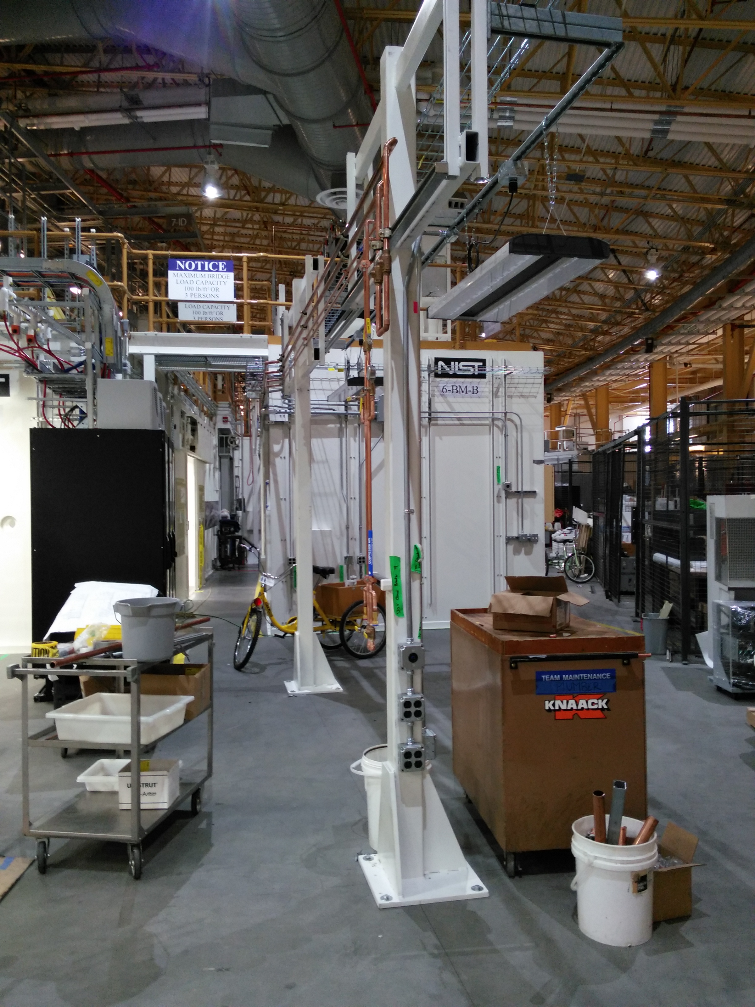
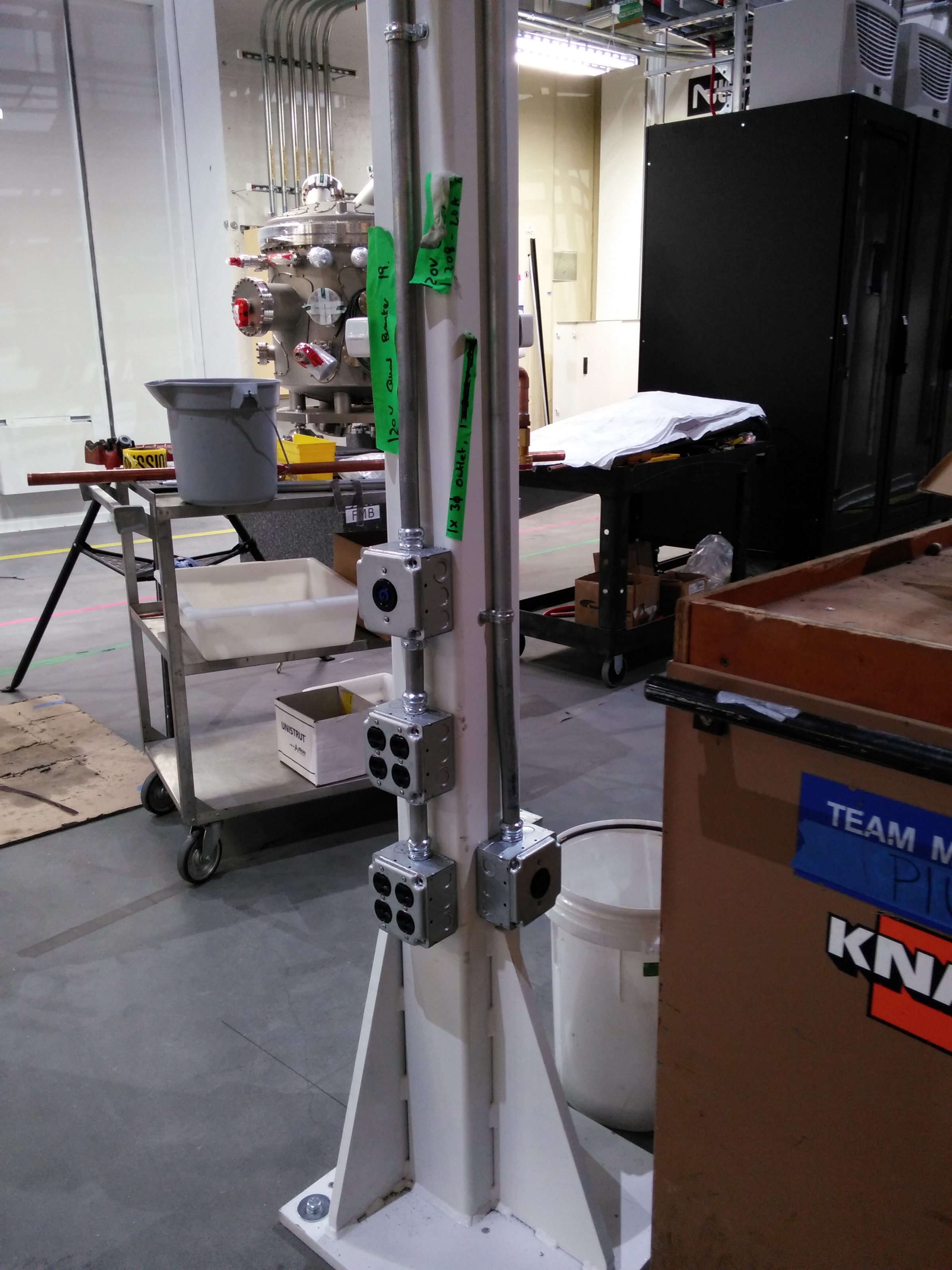
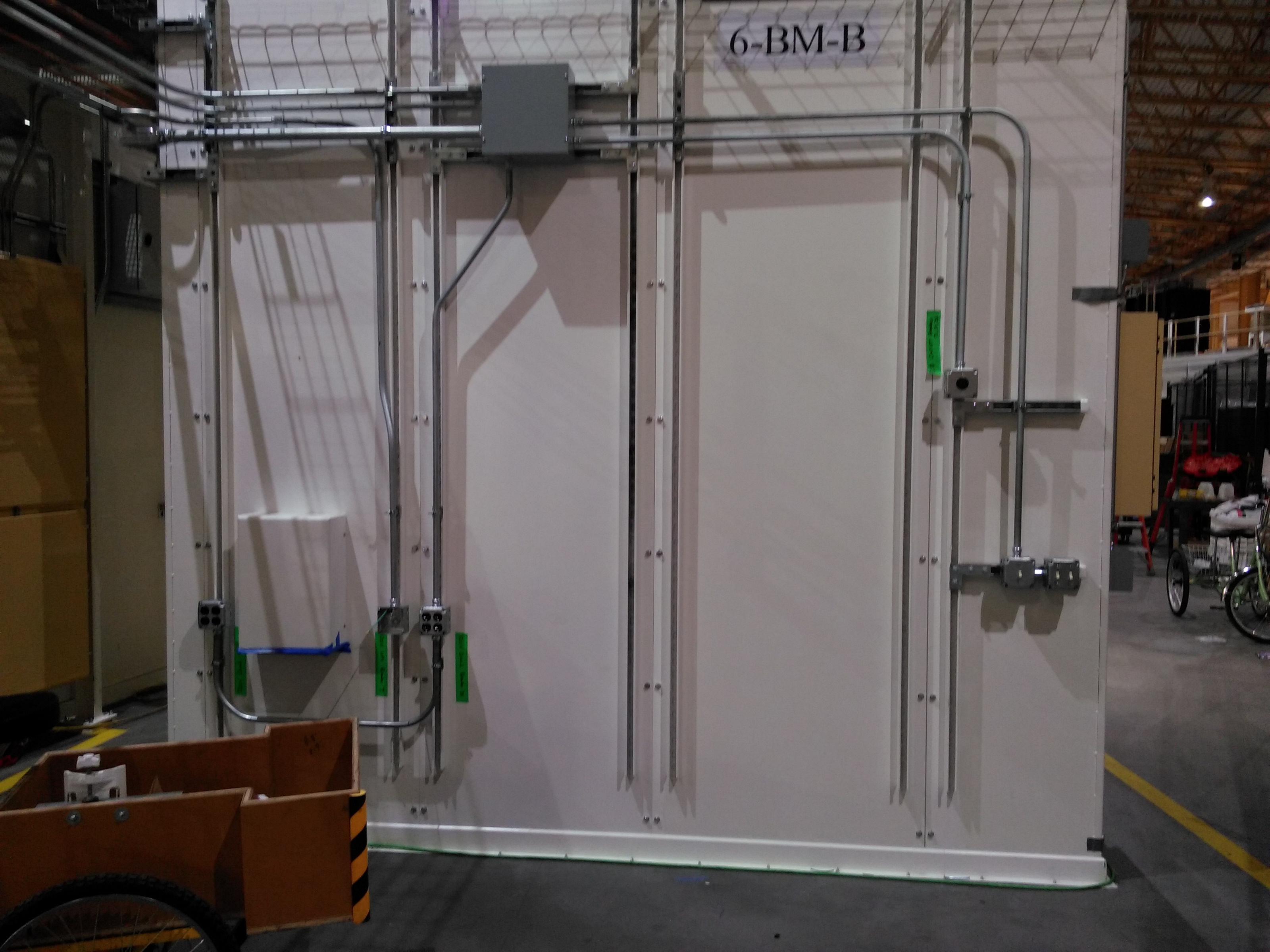
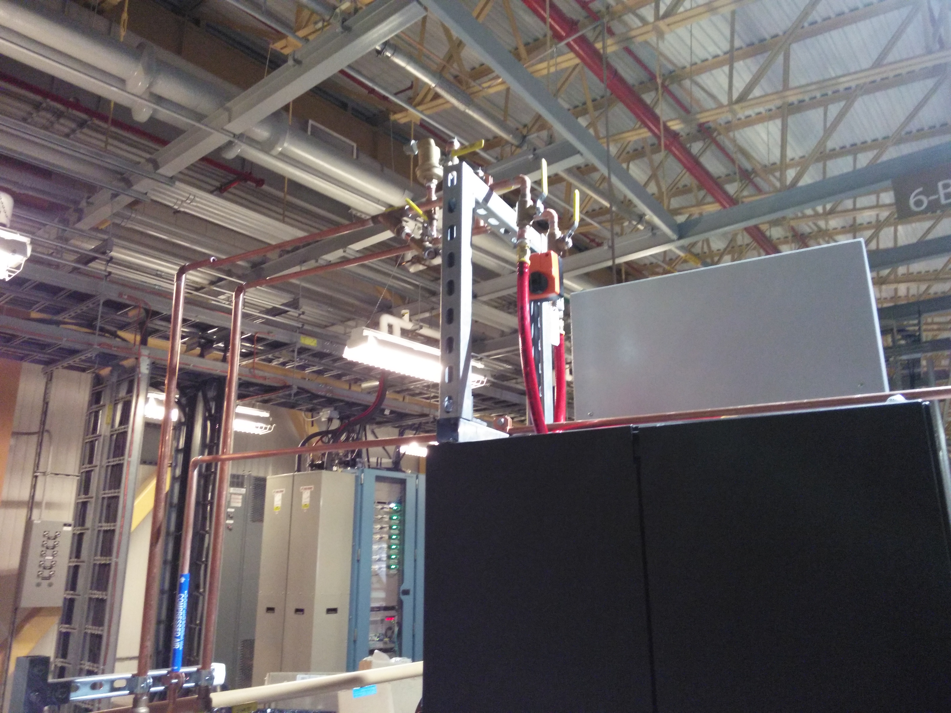
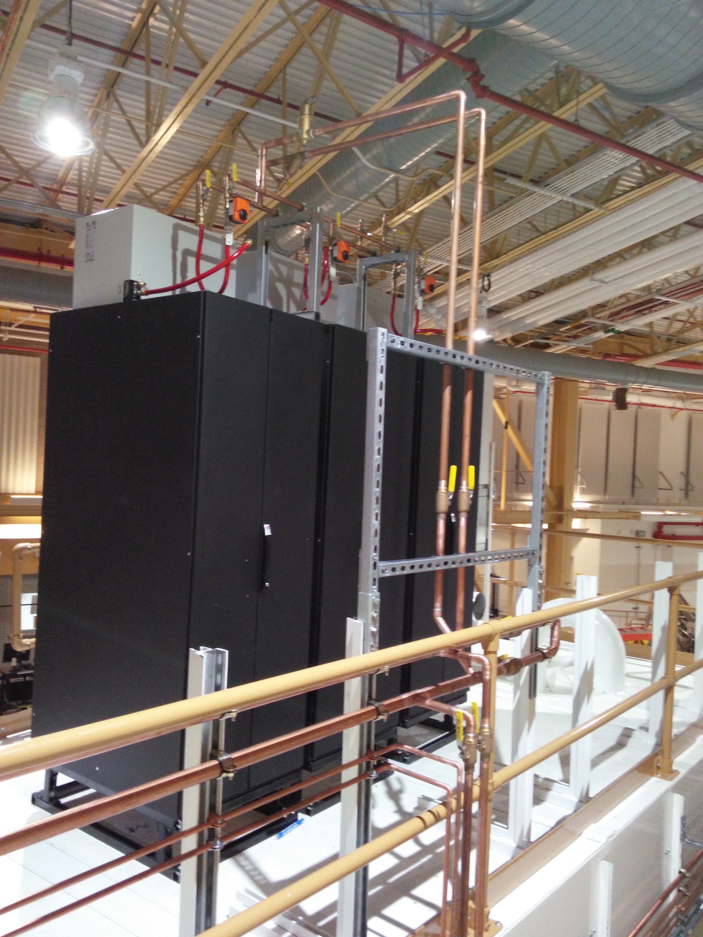
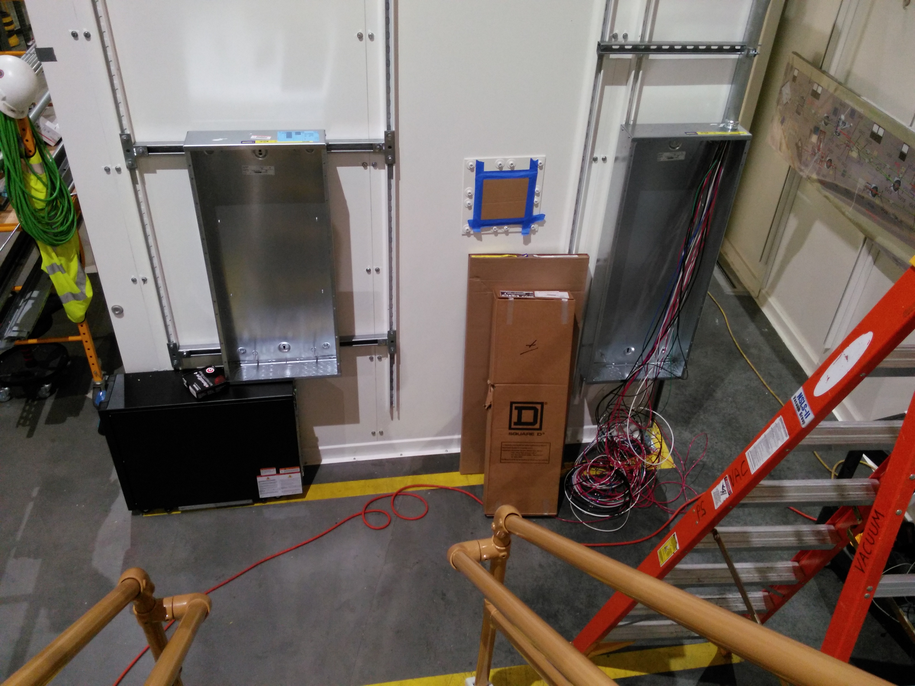
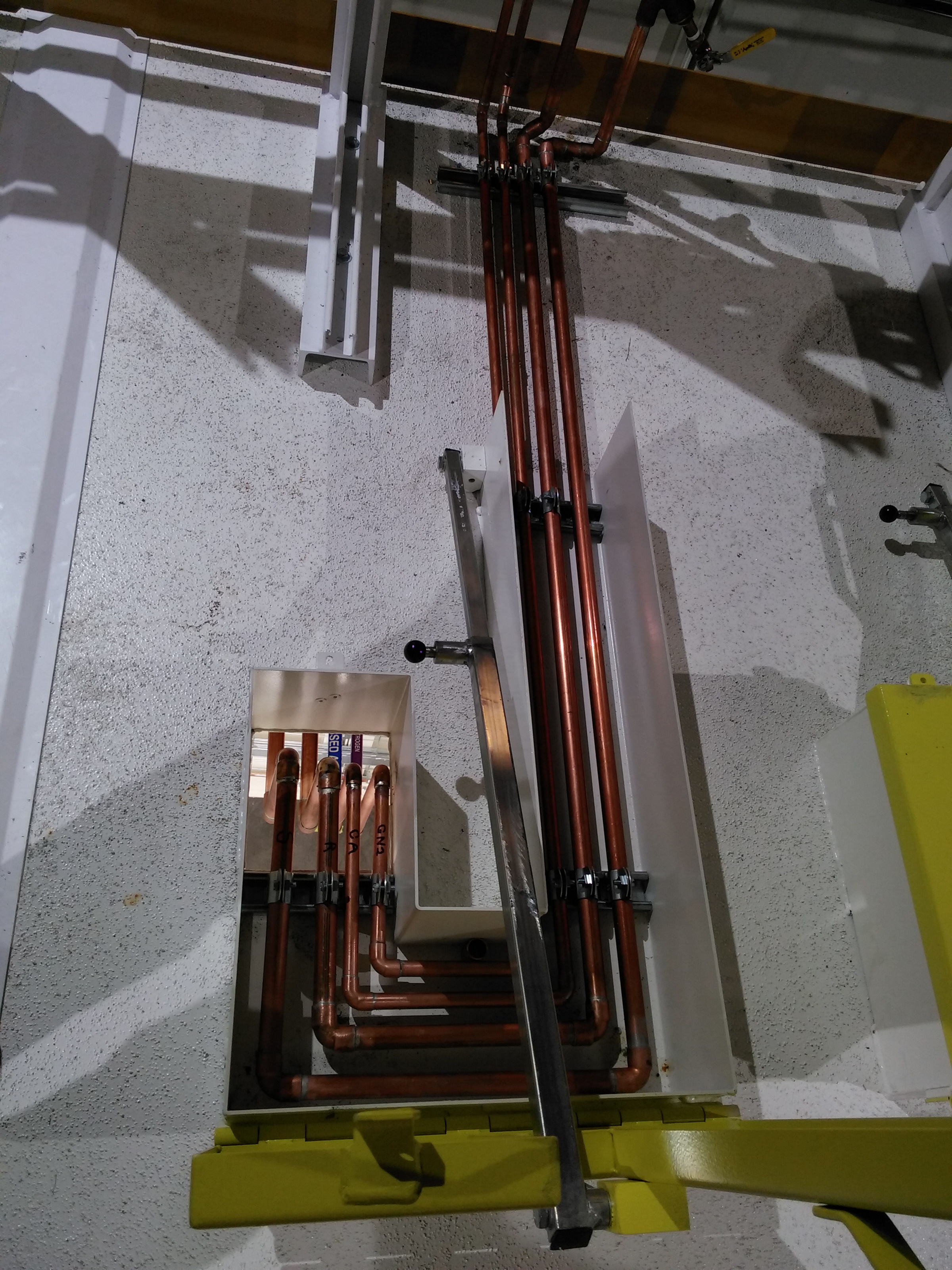
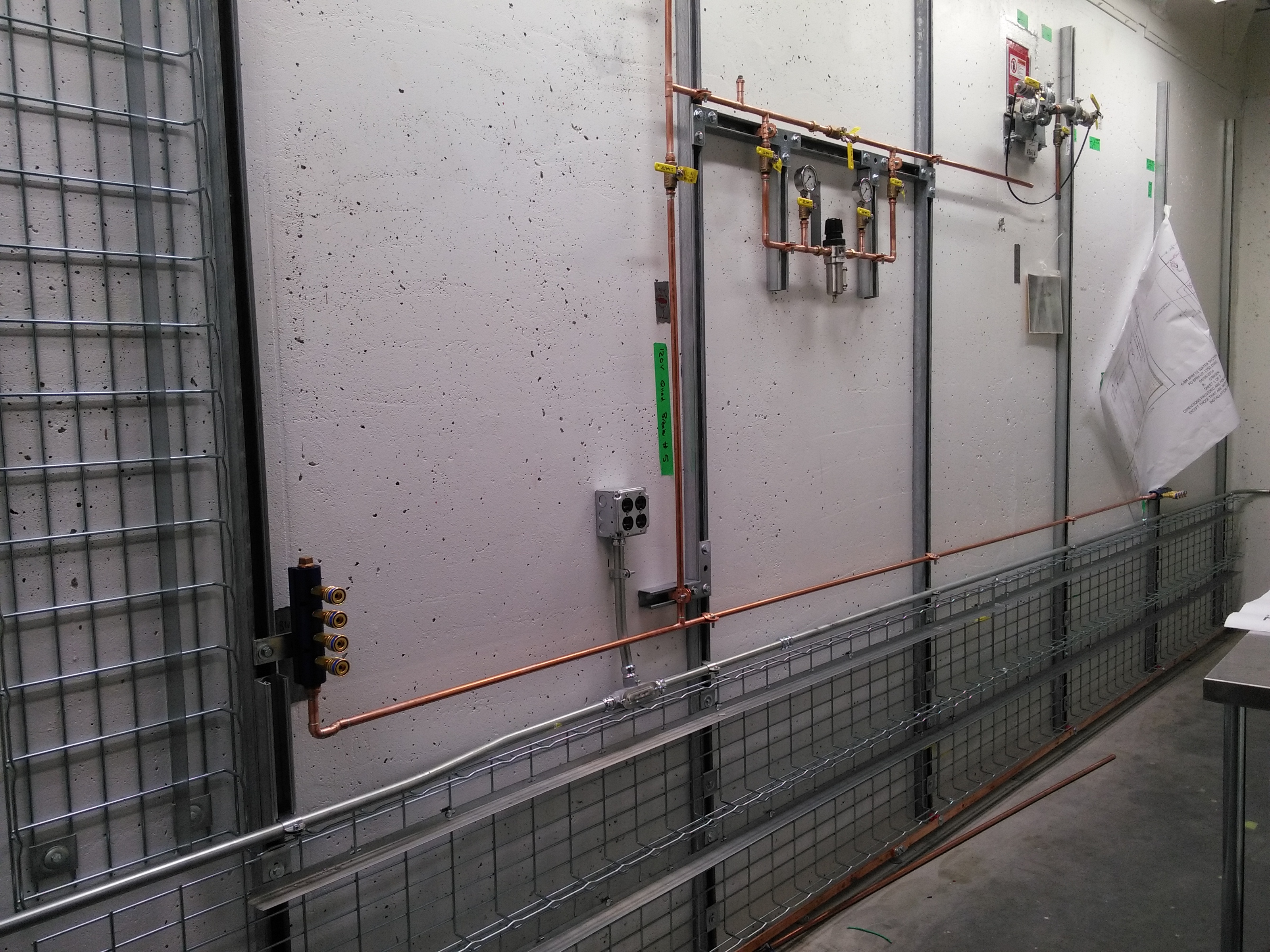
May 10, 2016
| Gas and power at pylon 3 | Close-up of power at pylon 3 | Power on downstream wall of 6BM-B | Rack plumbing, 6BM-A | Rack plumbing, 6BM-B | Power distribution panels, upstream wall of 6BM-A |
 |
 |
 |
 |
 |
 |
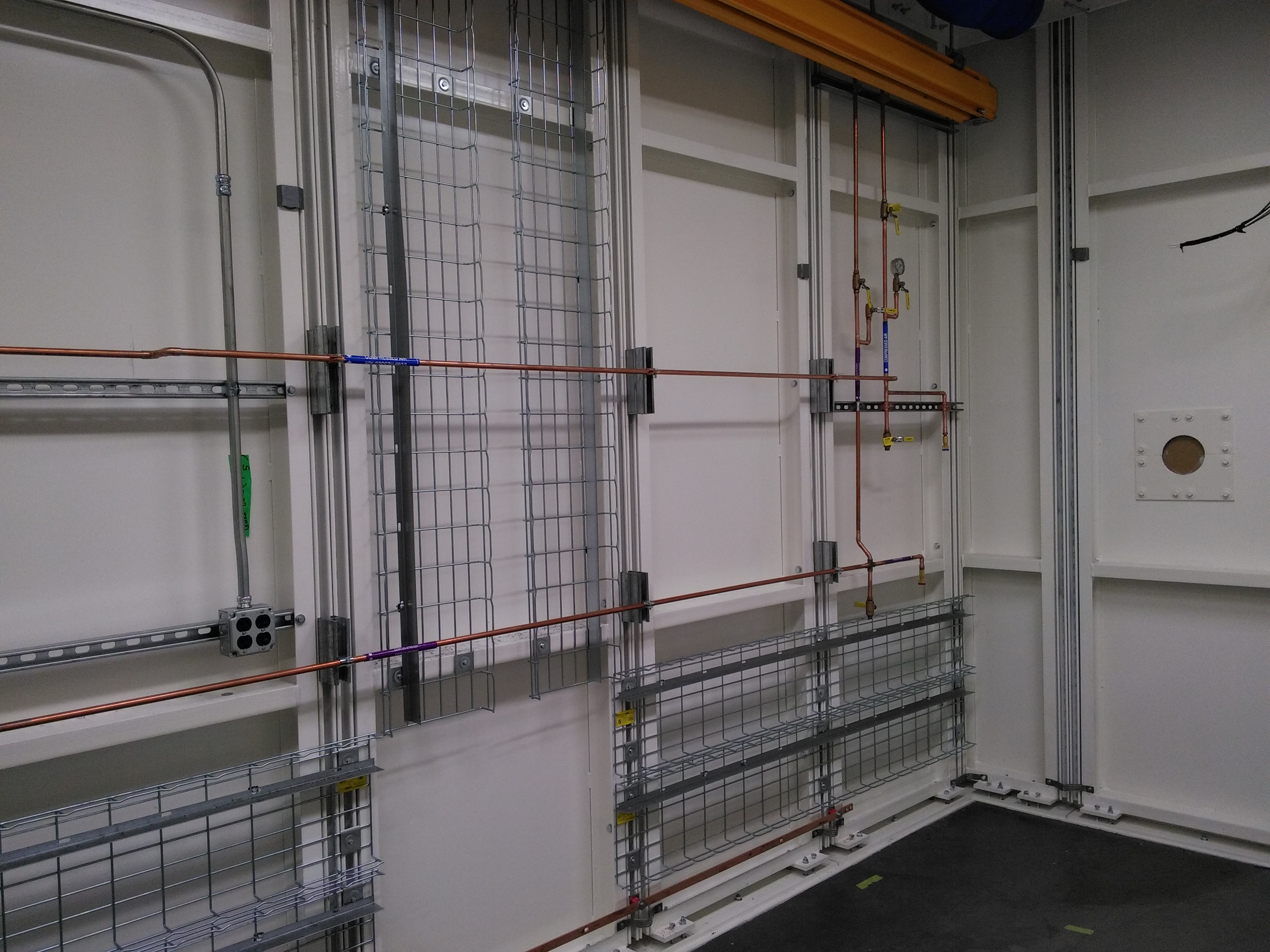
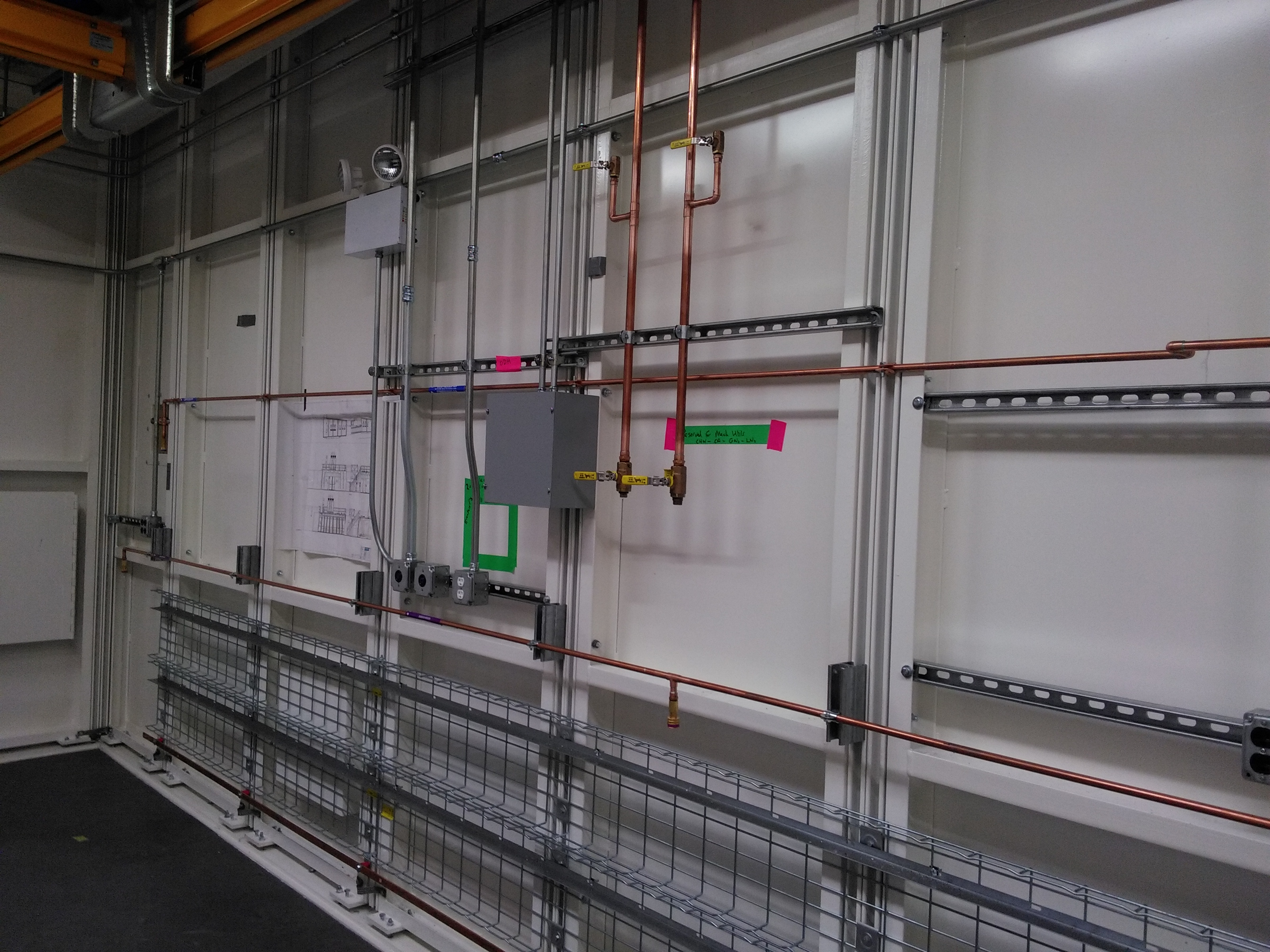
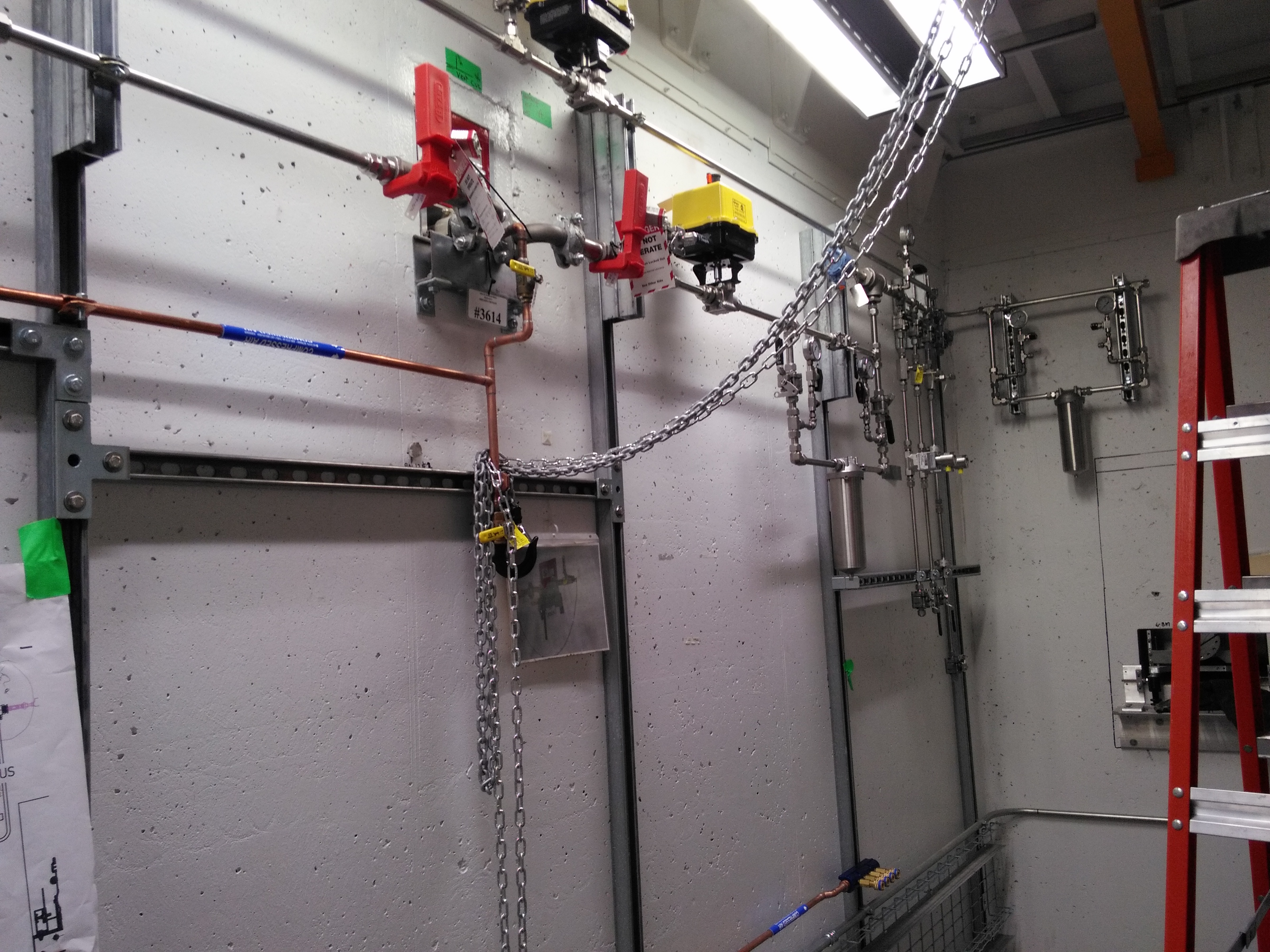
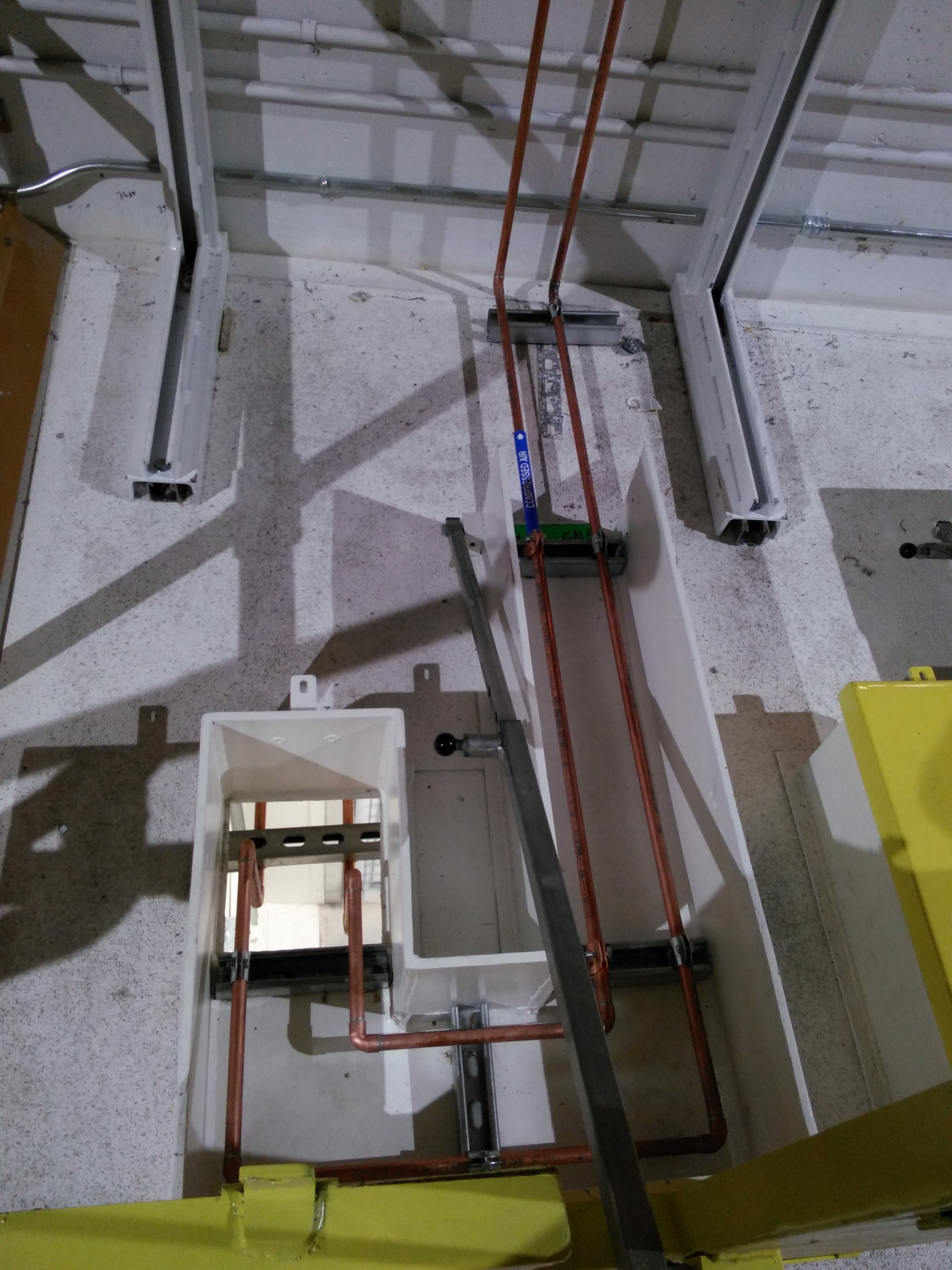
May 5, 2016
| Gas distribution in the B hutch | Gas distribution in the B hutch | Water distribution in the A hutch | Gas plumbing into the A hutch | Gas and water distribution between the hutches | Lights and services downstream of the B hutch |
 |
 |
 |
 |
 |
 |
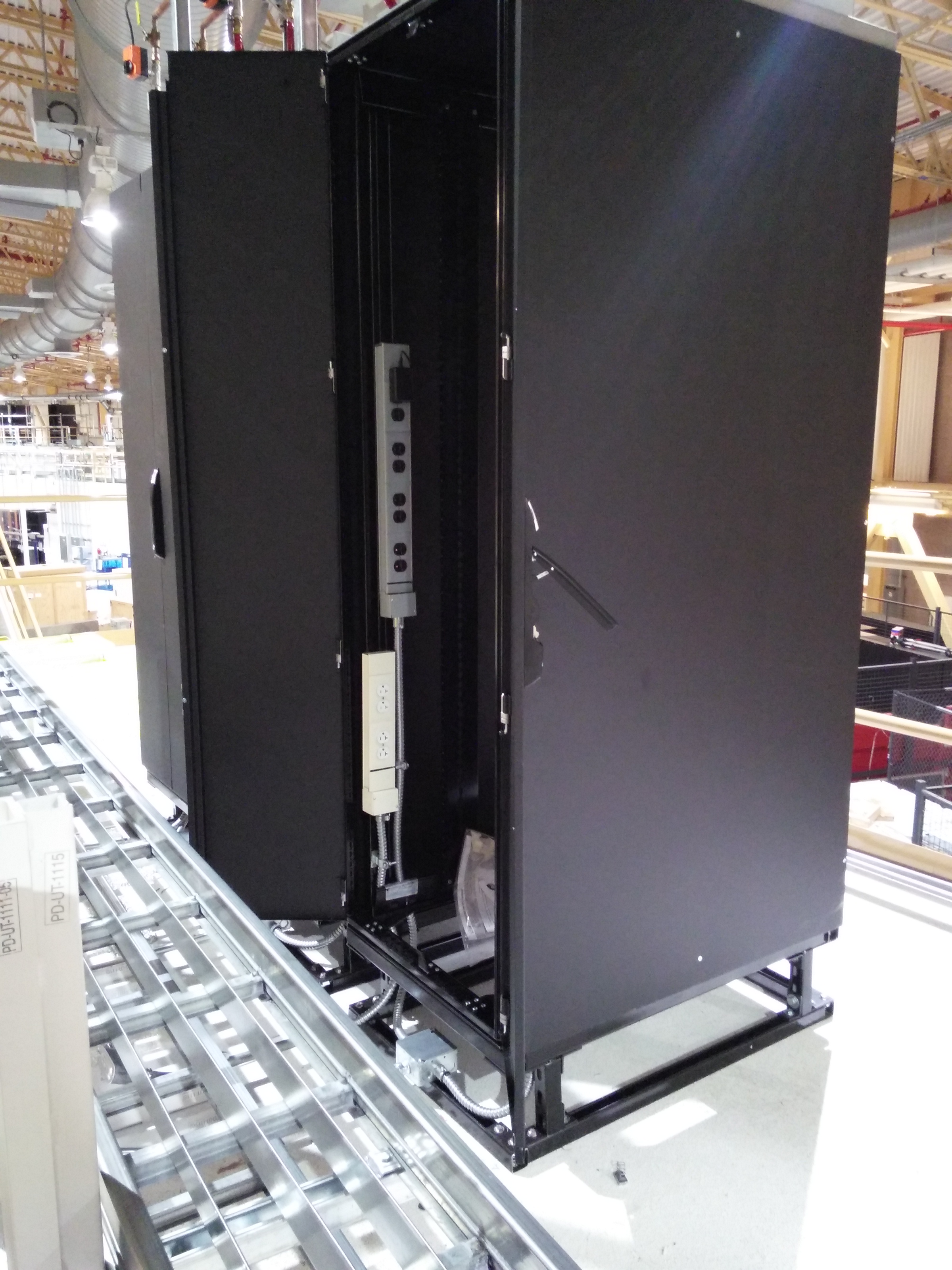
April 29, 2016
| Gas plumbing into the B hutch | We now have racks on the B hutch! | Services extending out to the sample prep area | Services to the rack on the A hutch |
 |
 |
 |
 |
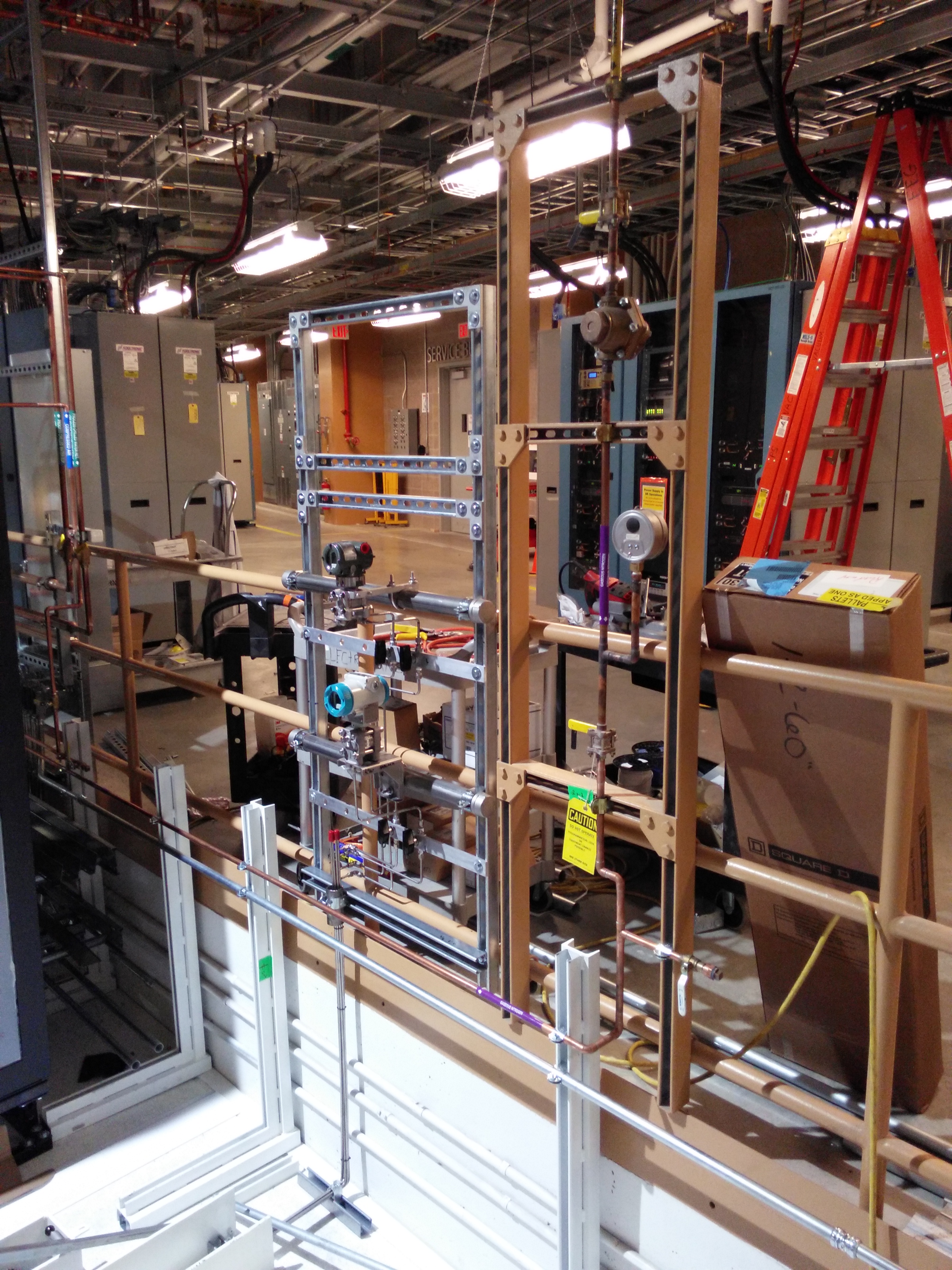
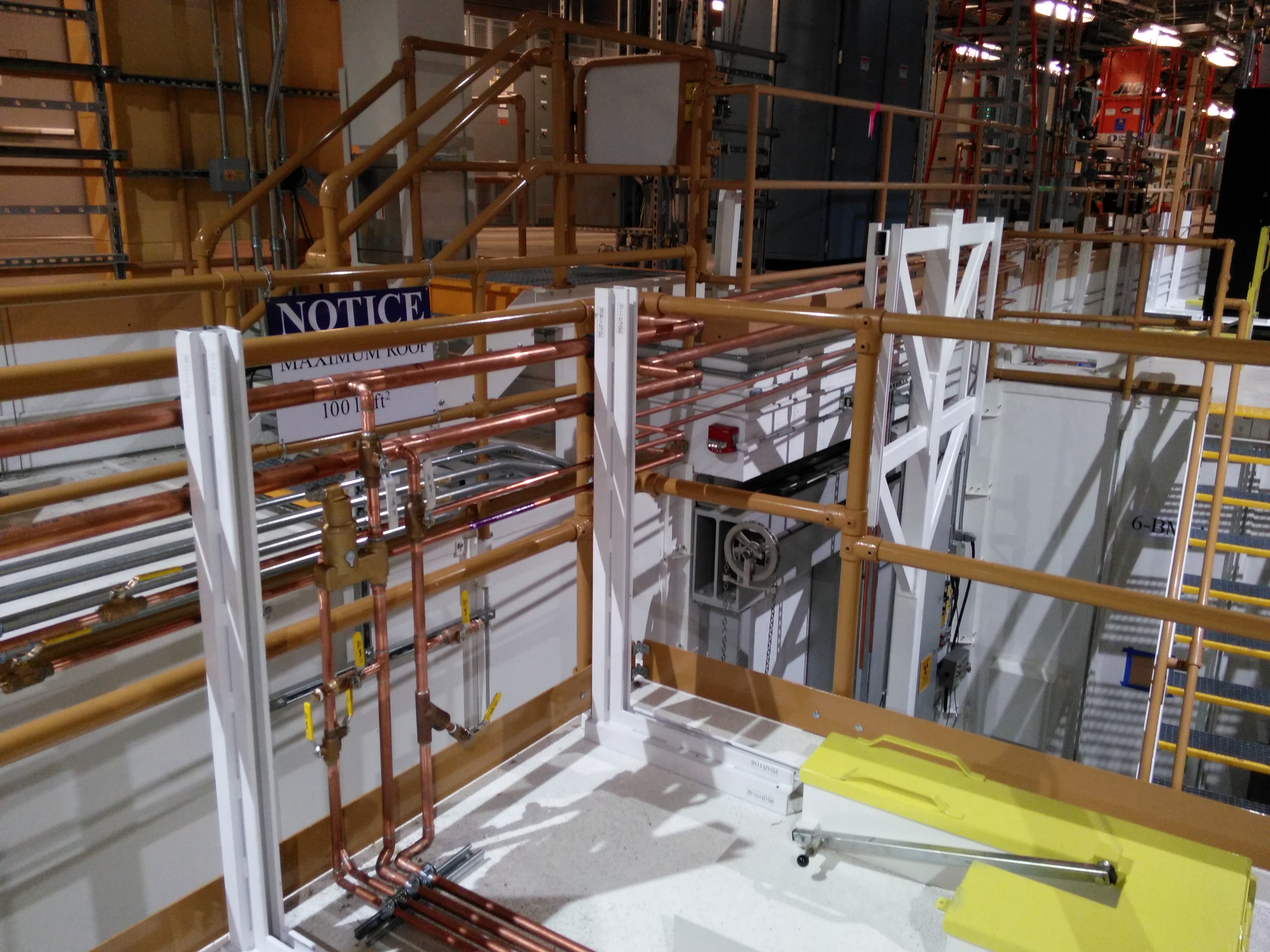
April 21, 2016
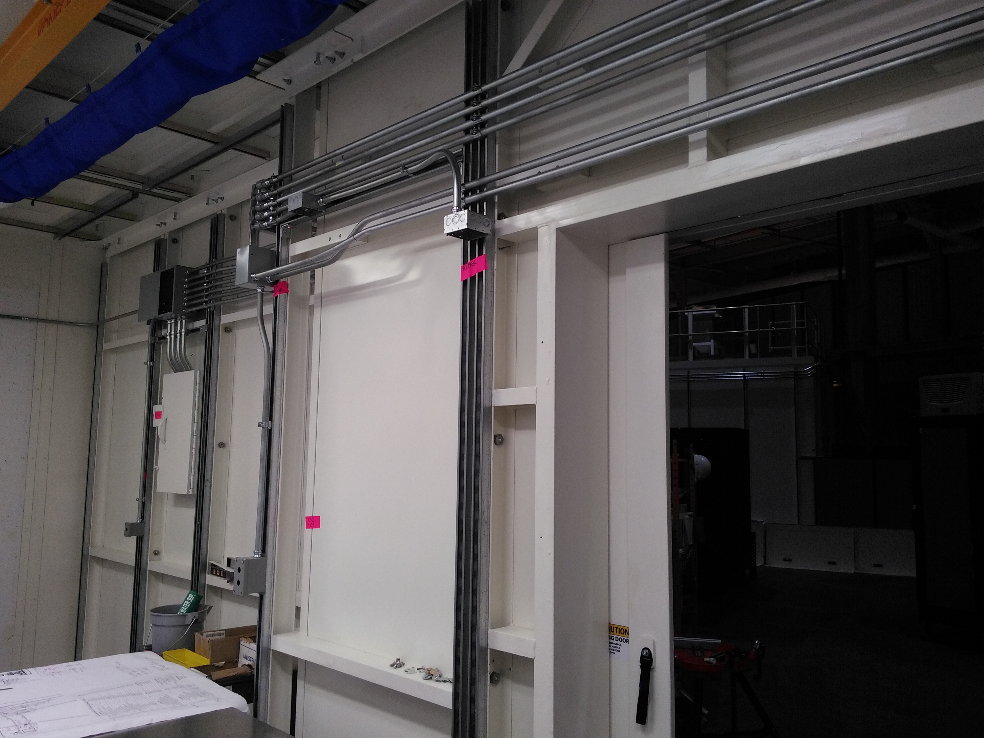
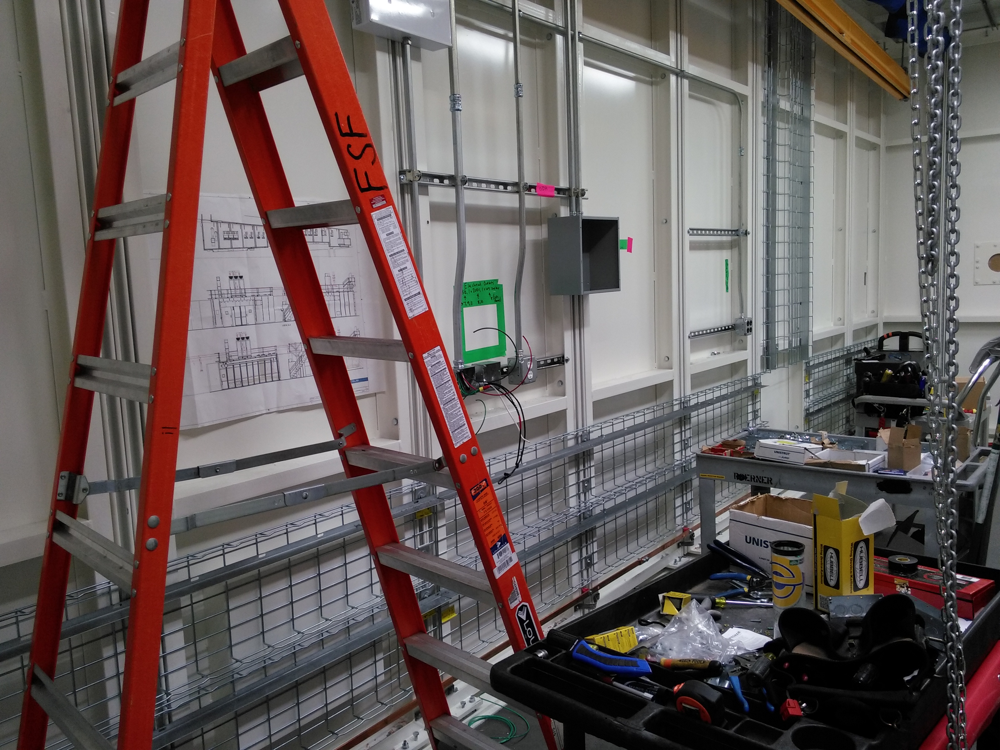
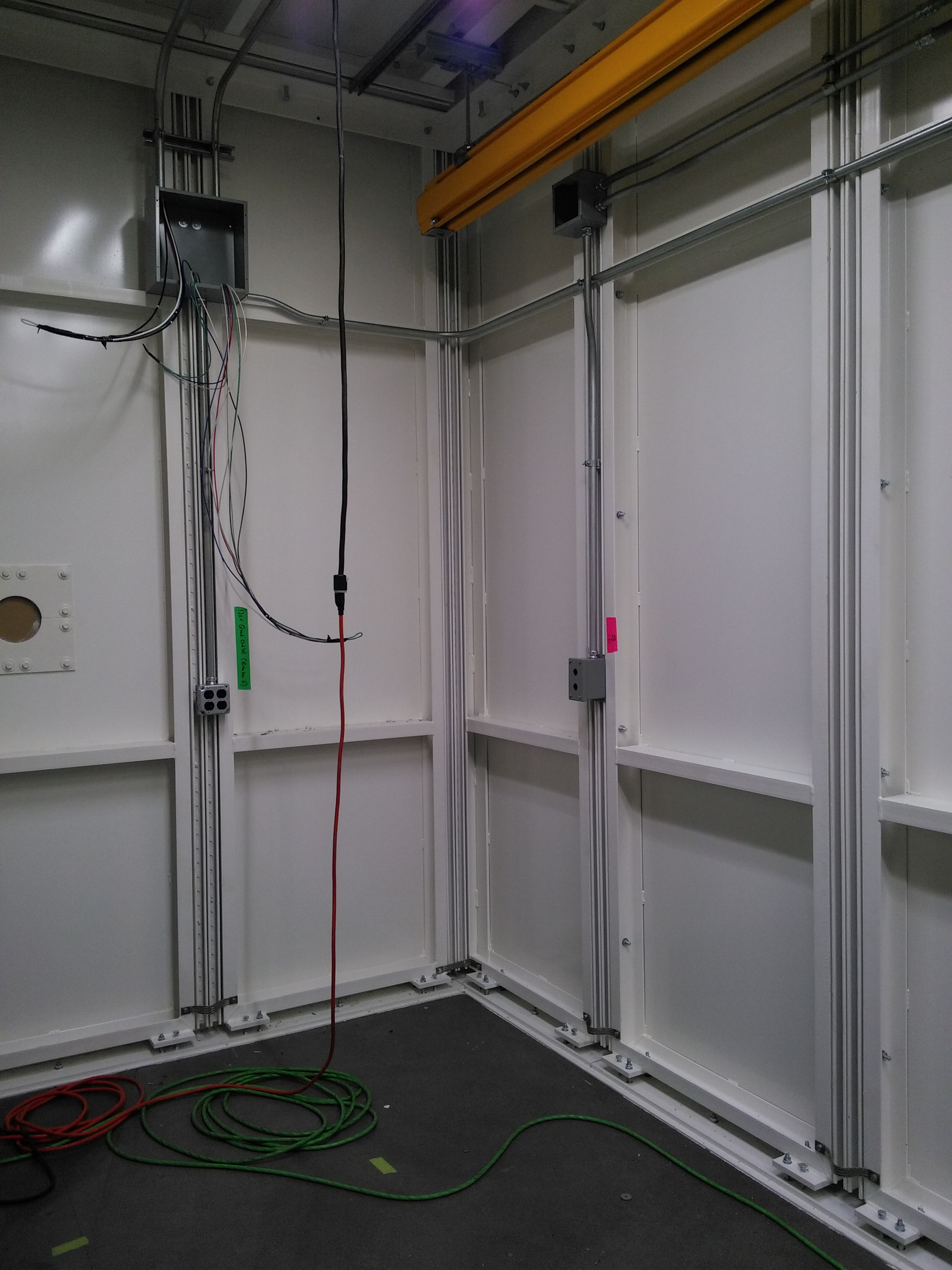
Progress on utilities installation has been amazing! The electricians and plumbers are doing bang-up work.
| 6BM-A utilities, inboard wall | PPS in 6BM-A | 6BM-B utilities, inboard wall | Electrical in 6BM-B | Racks awaiting installation | Plumbing on pylon 1 | Plumbing on Pylons 2 and 3 | Plumbing distribution, 6BM-B |
 |
 |
 |
 |
 |
 |
 |
 |
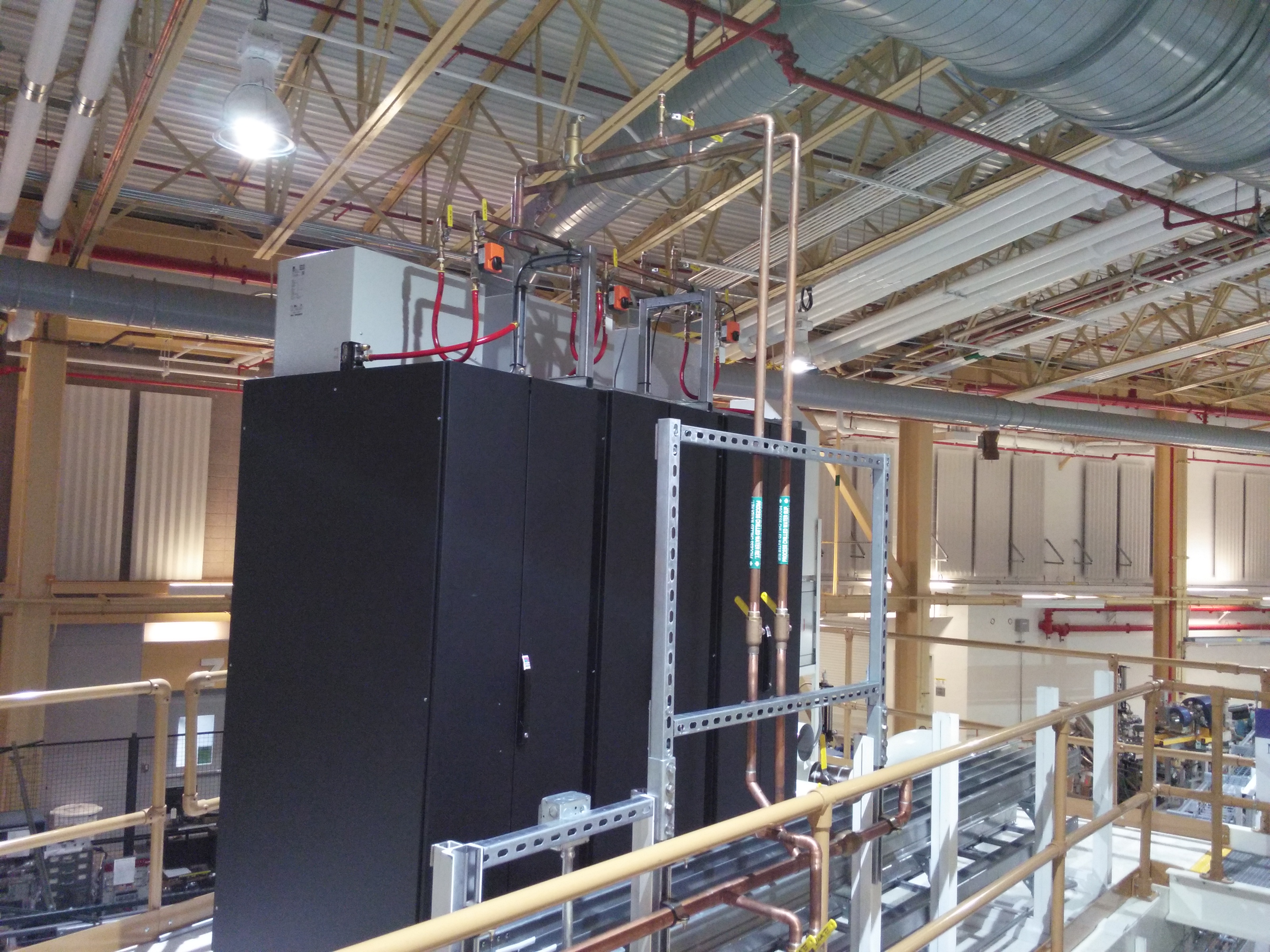
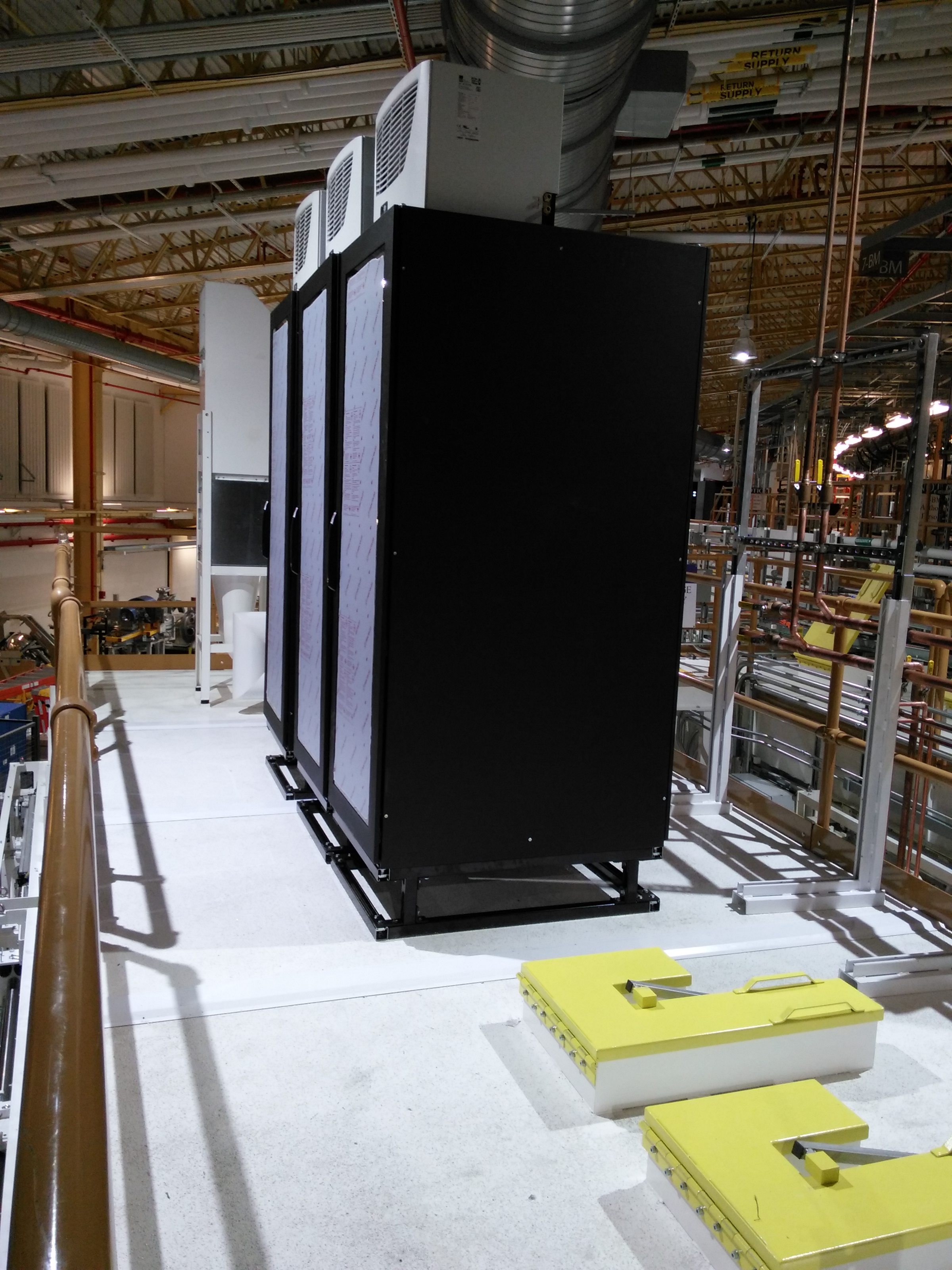
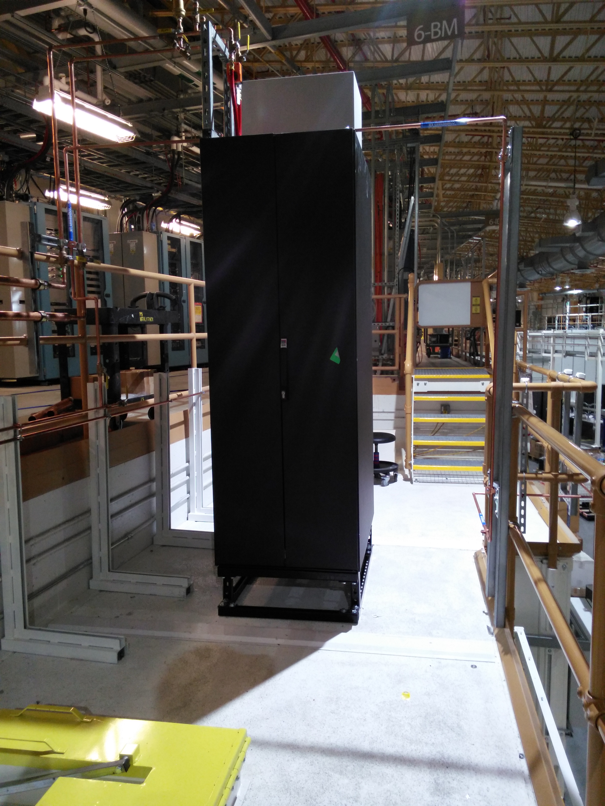
April 13, 2016
Today, an electronics rack was lifted to the roof of the 6BM-A hutch and installed.
| 6BM-A vacuum electronics rack | Water and gas plumbing |
 |
 |
April 5, 2016
Utilities installation has begun!
| Pylon #1 | Pylons 2 and 3 | Pylon #1 from the 6BM-A roof | Pylons 2 and 3 from the 6BM-B roof | Pylon 1 from the 6BM-B roof |
 |
 |
 |
 |
 |
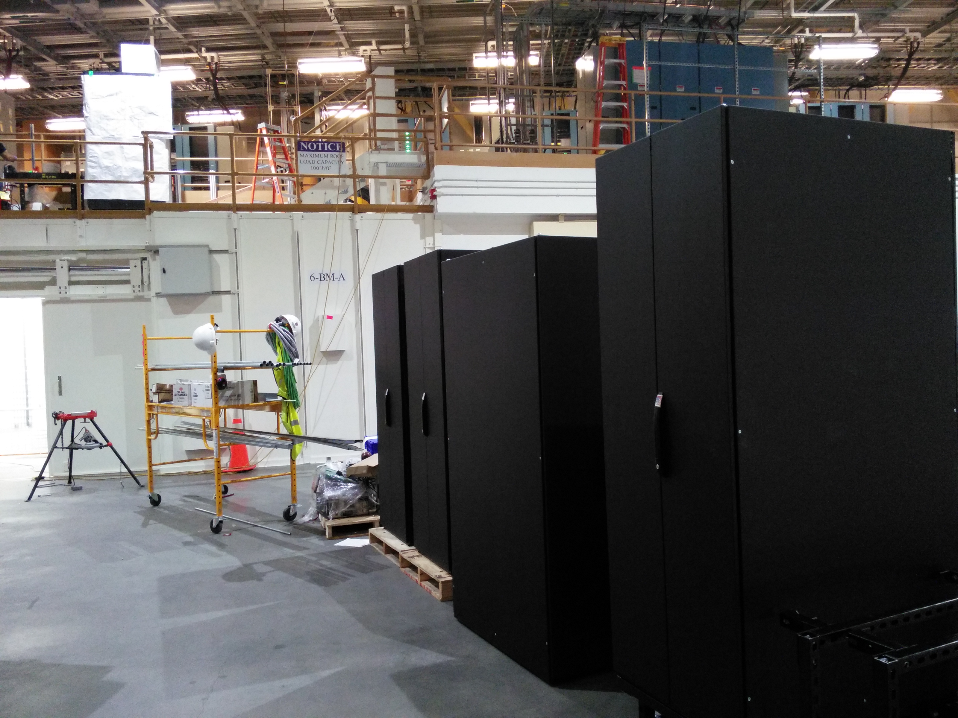
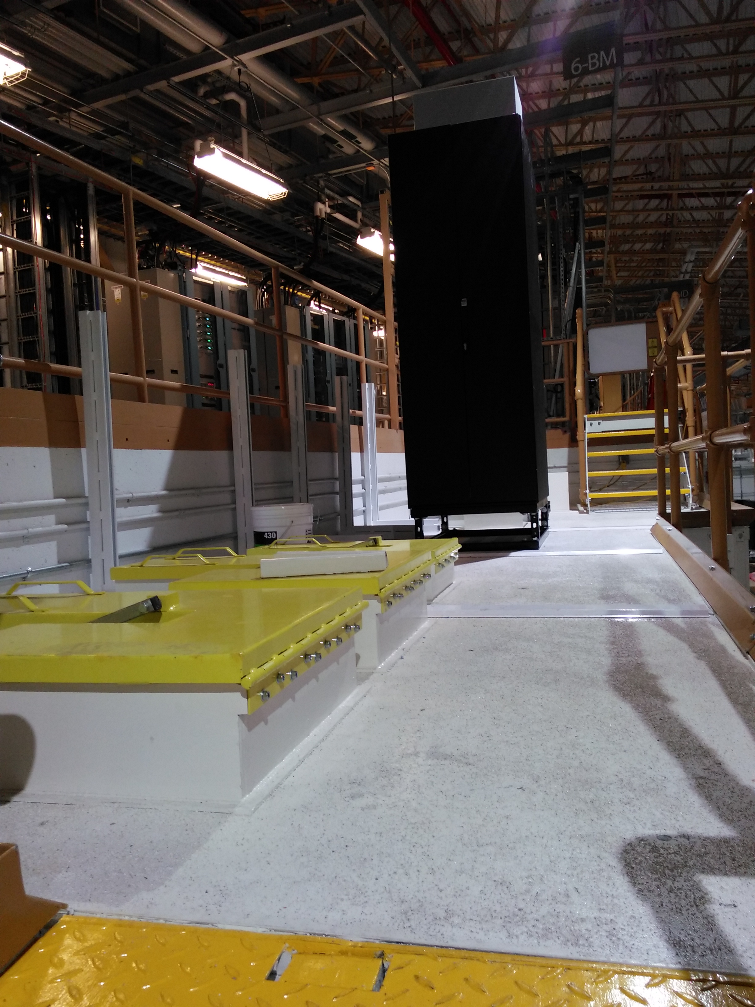
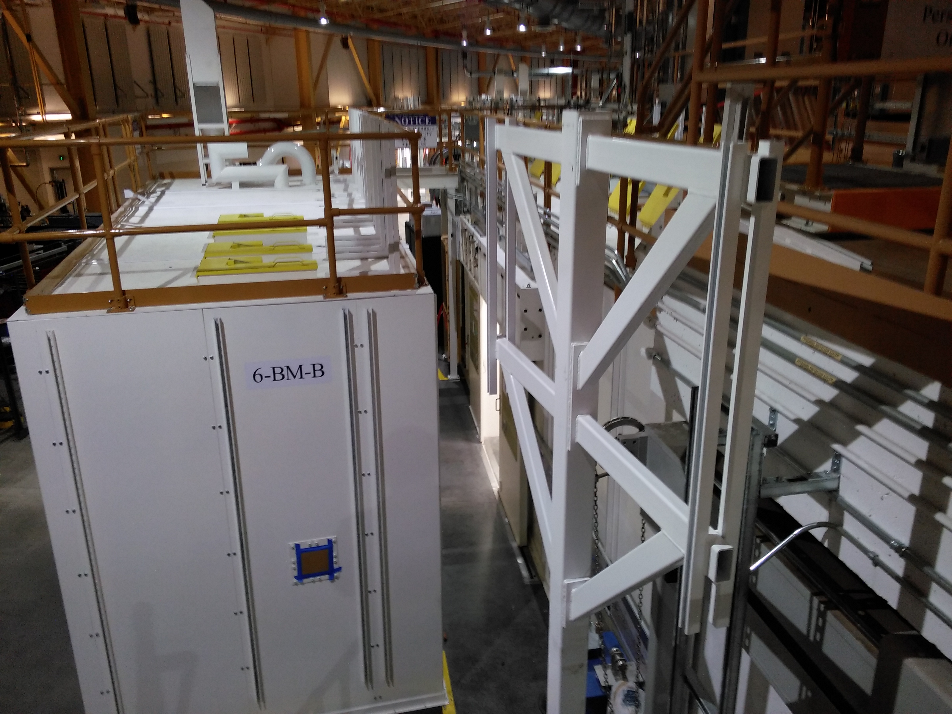
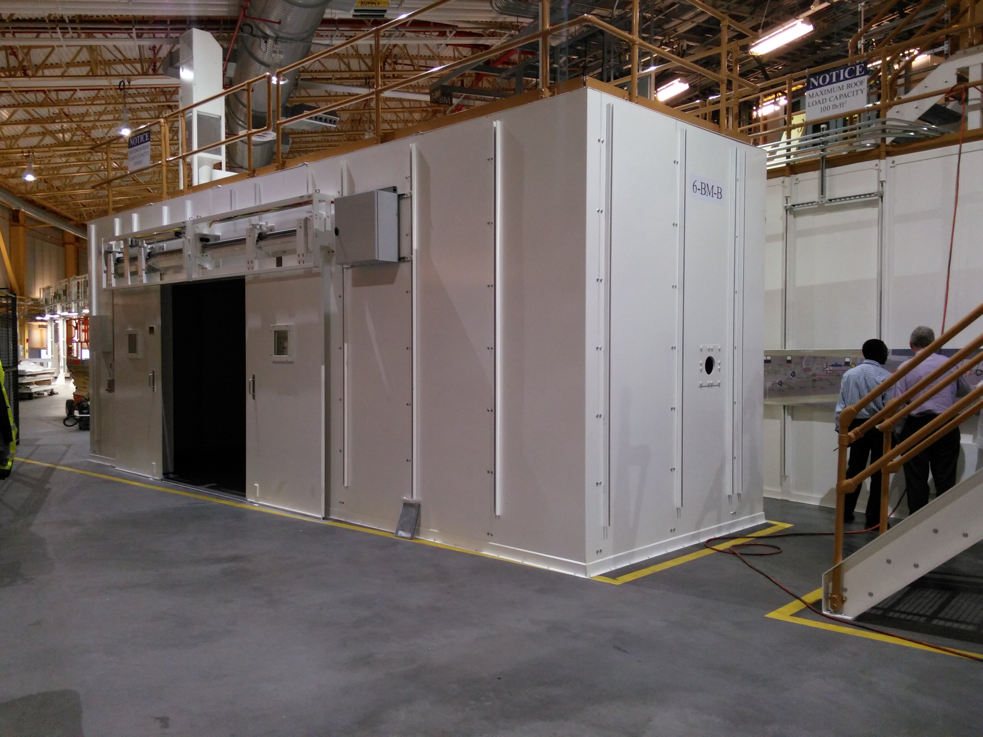
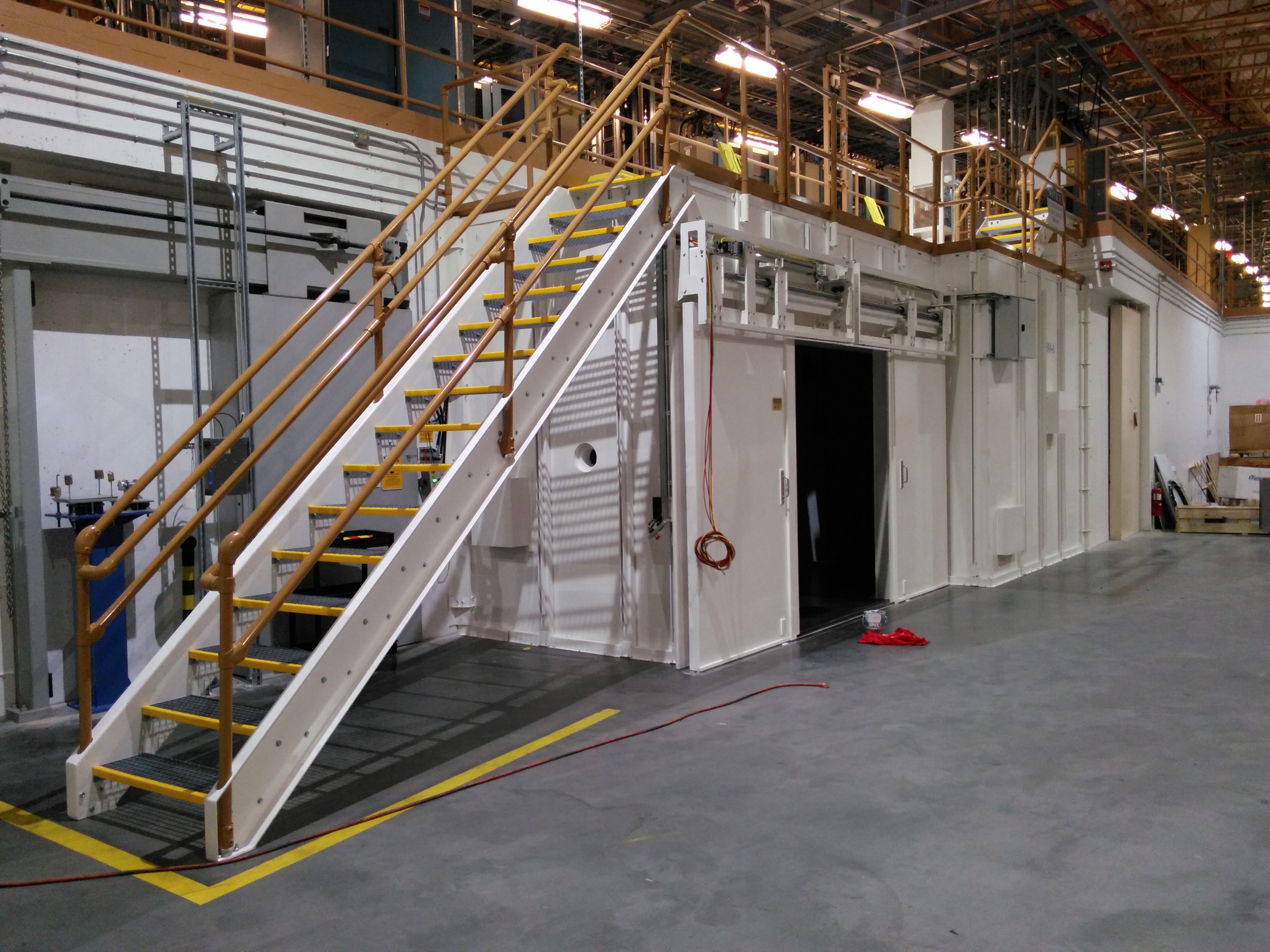
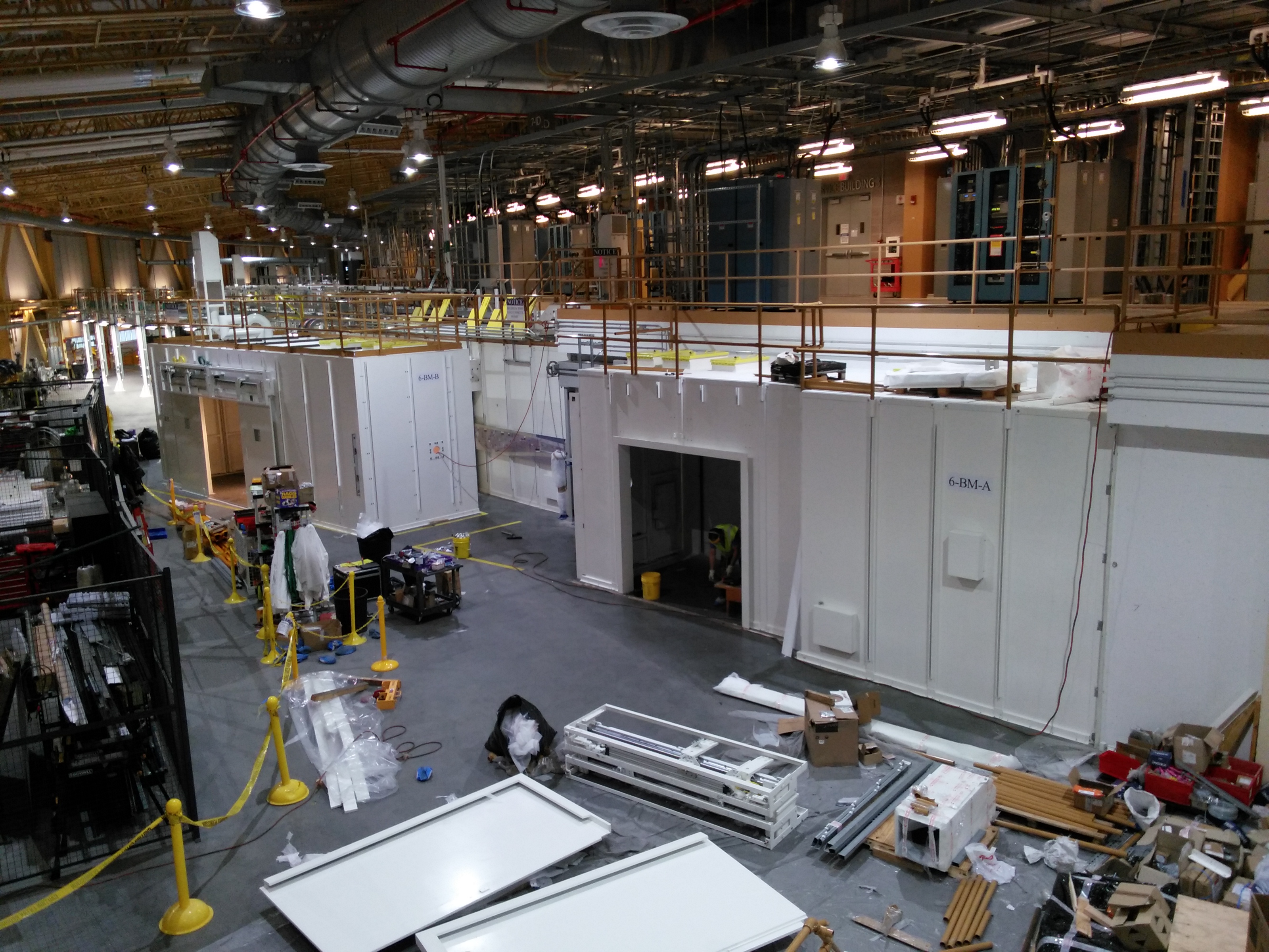
December 22, 2015
Just in time for a jolly, jolly holiday, Caratelli finished the BMM hutches. Look how lovely they are!
Ground level
| The B hutch | The staircase | The A hutch |
 |
 |
 |
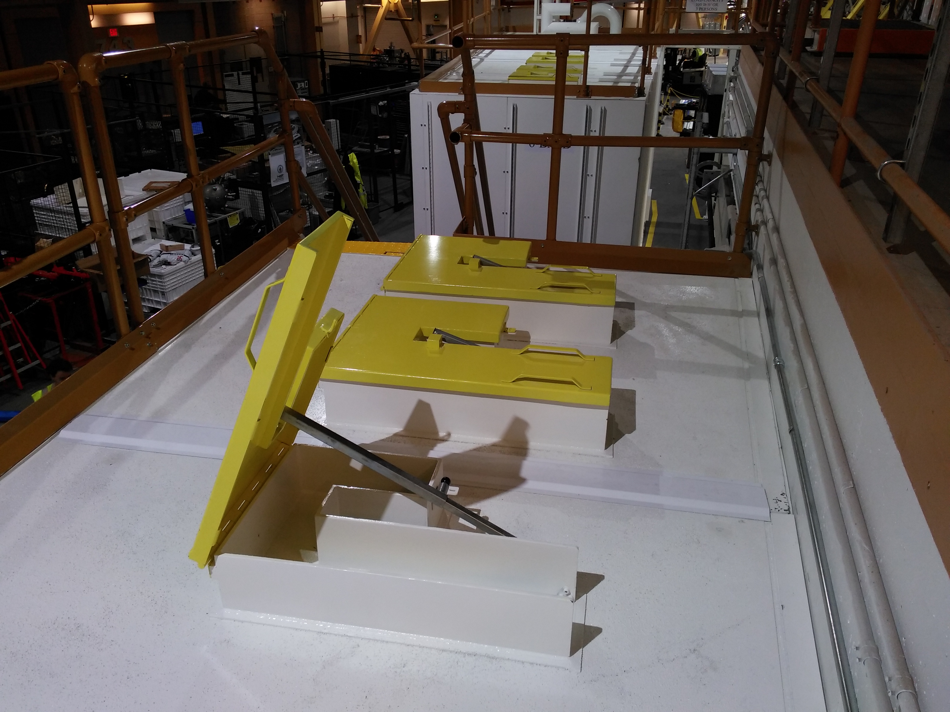
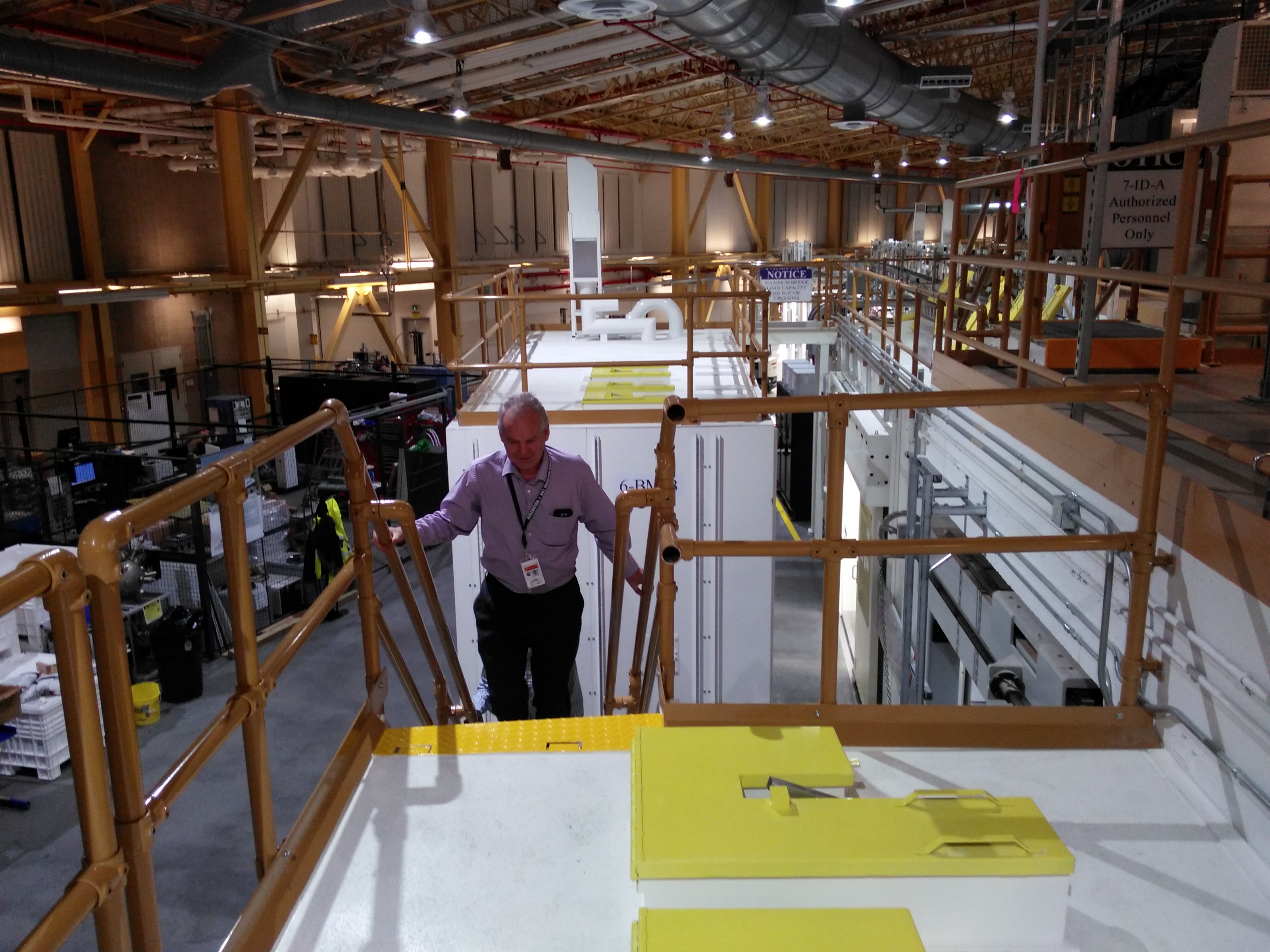
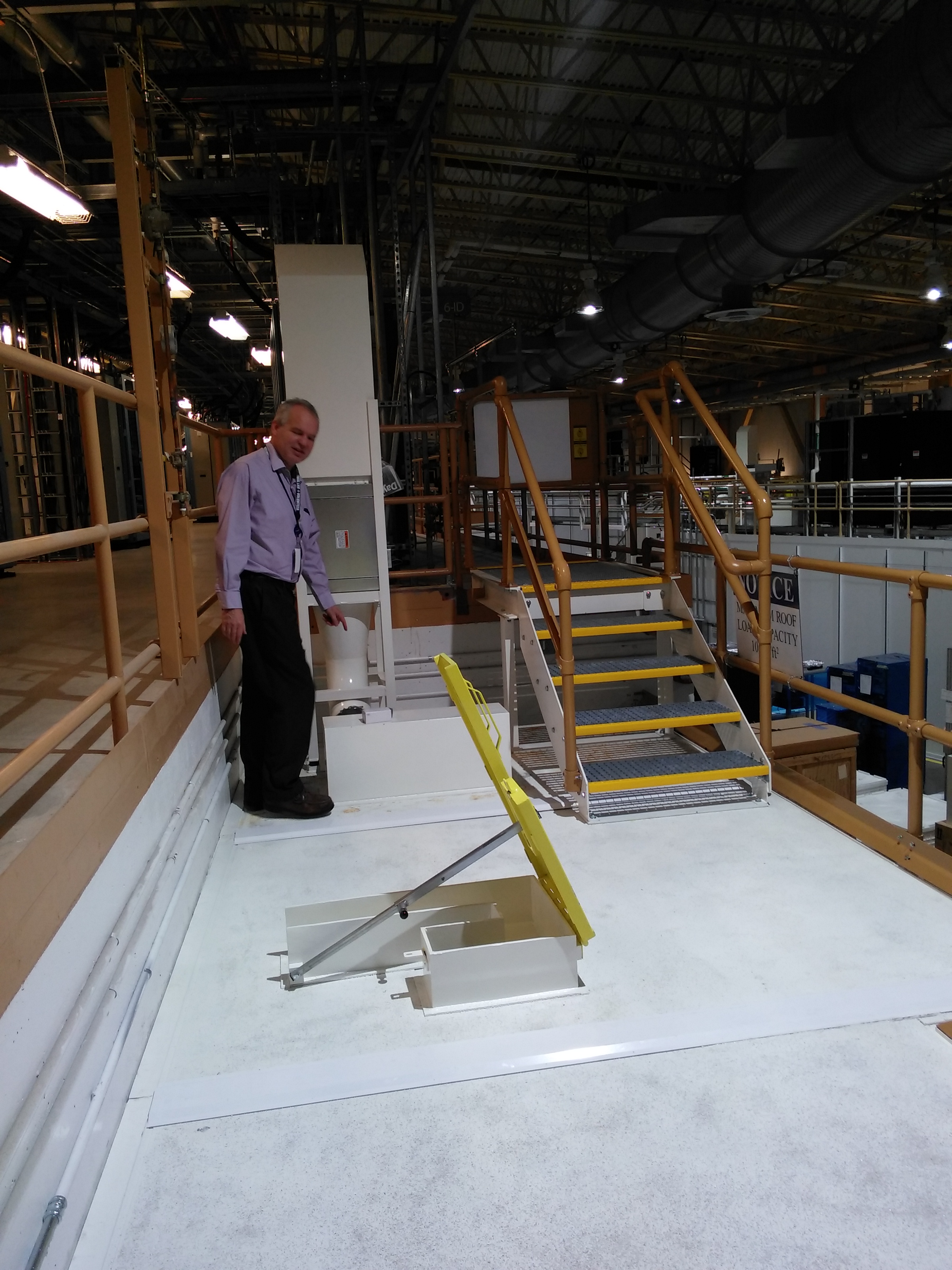
A hutch roof
| Labyrynths | Andy ascending the staircase | Elevated view of B hutch | Ventilation and stair to mezzanine | Ventilation |
 |
 |
 |
 |
 |
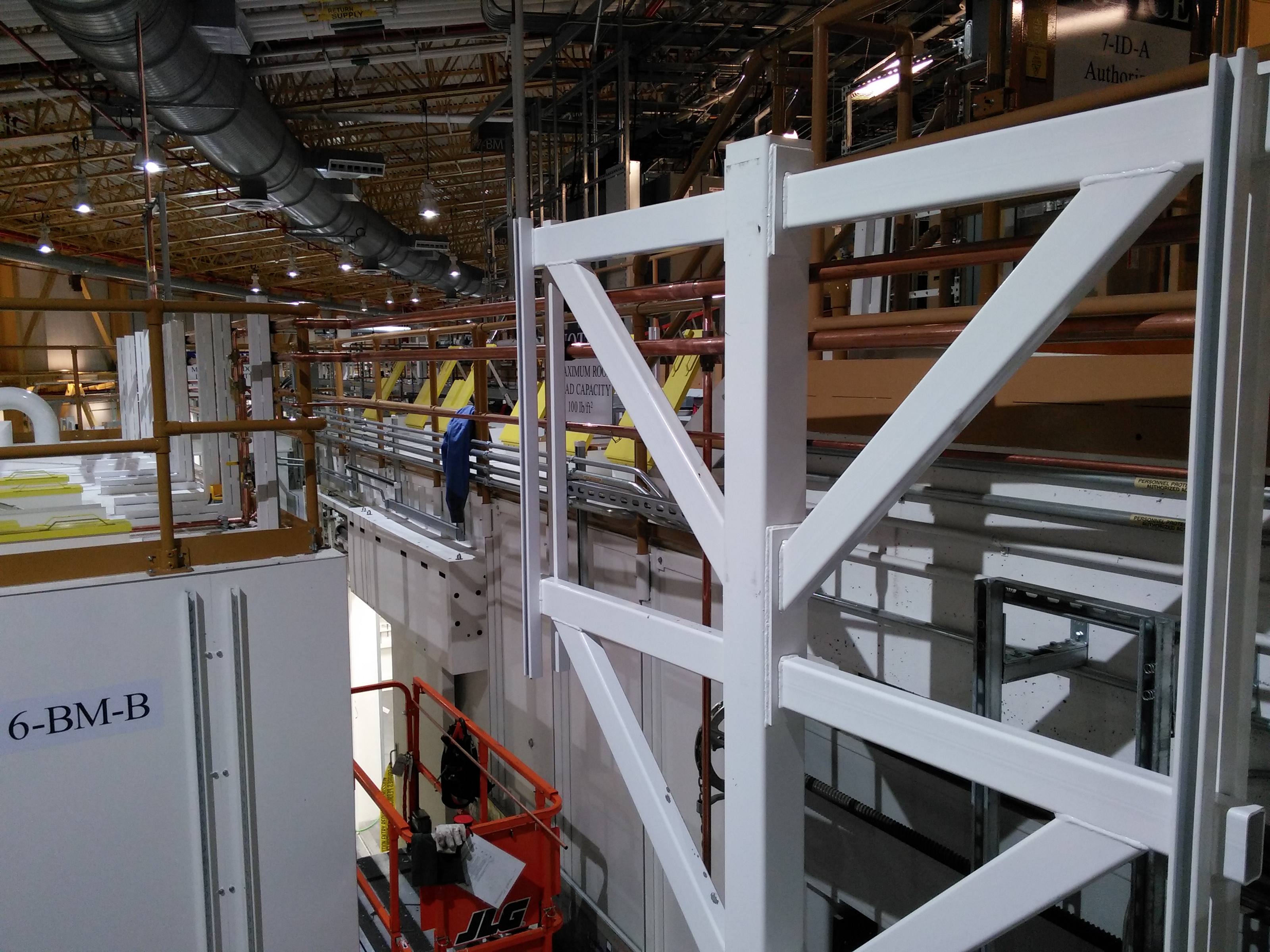
B hutch roof
| View from 7ID-A roof | Andy approaches the bridge | Looking upstream |
 |
 |
 |
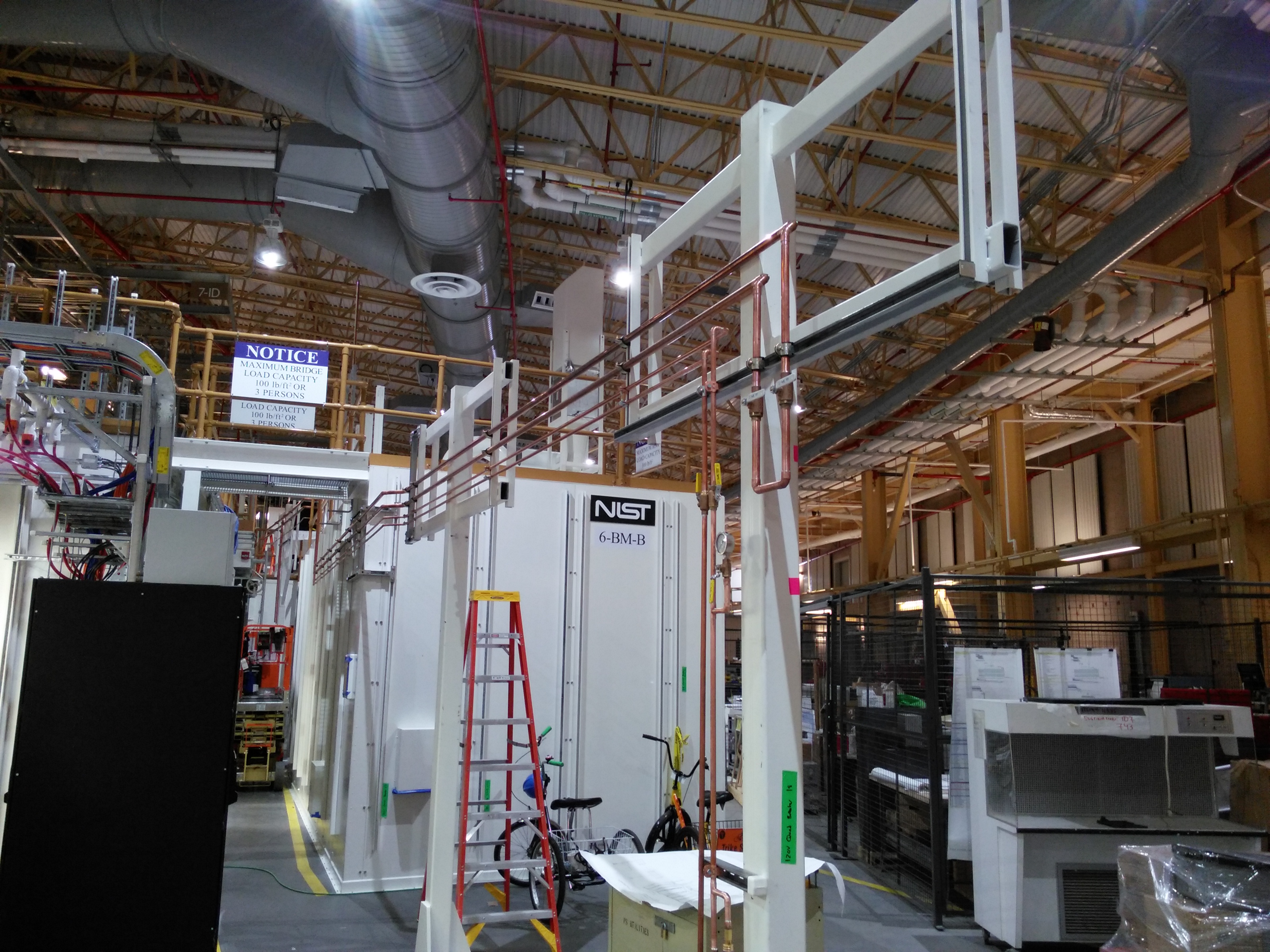
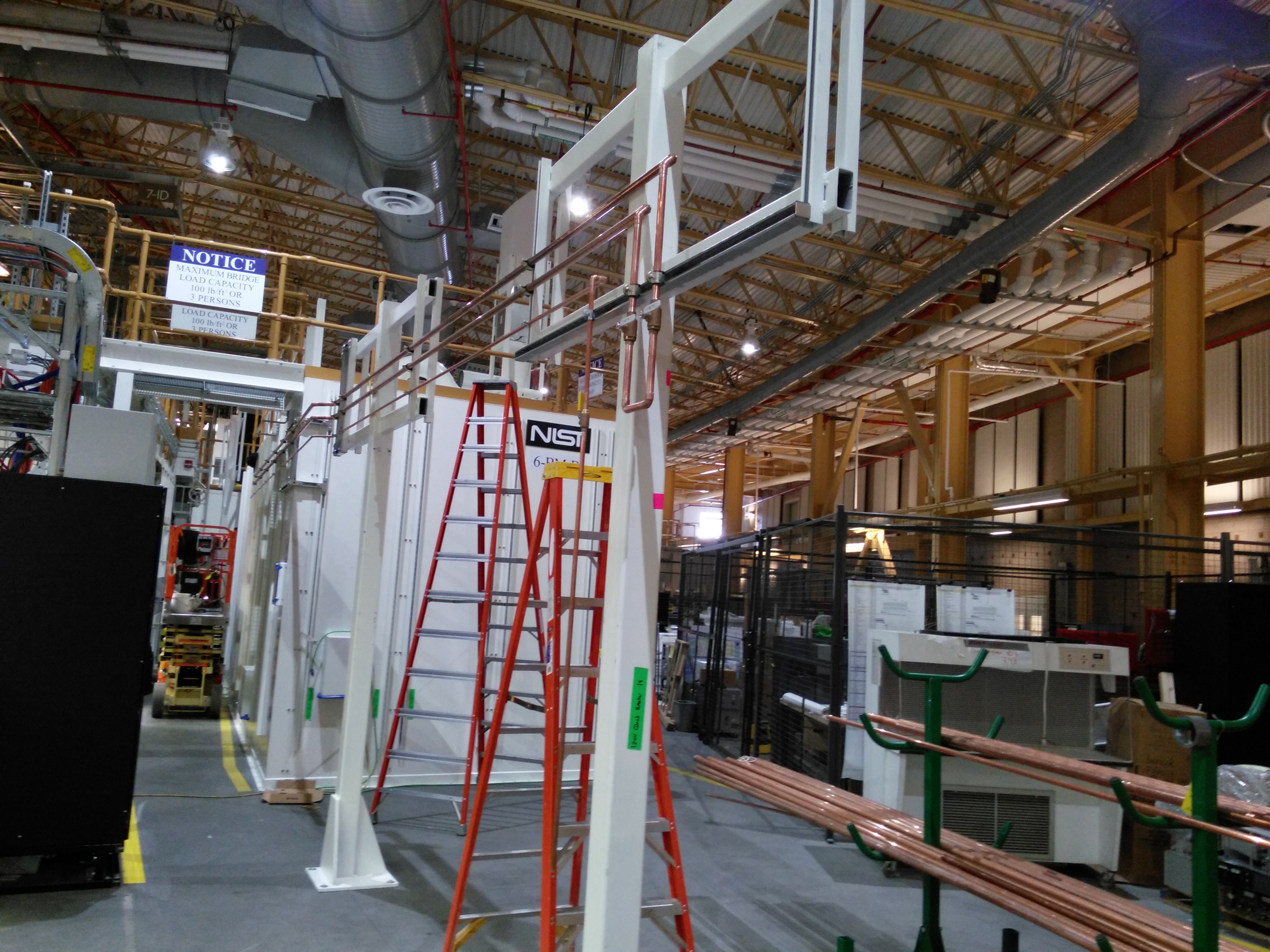
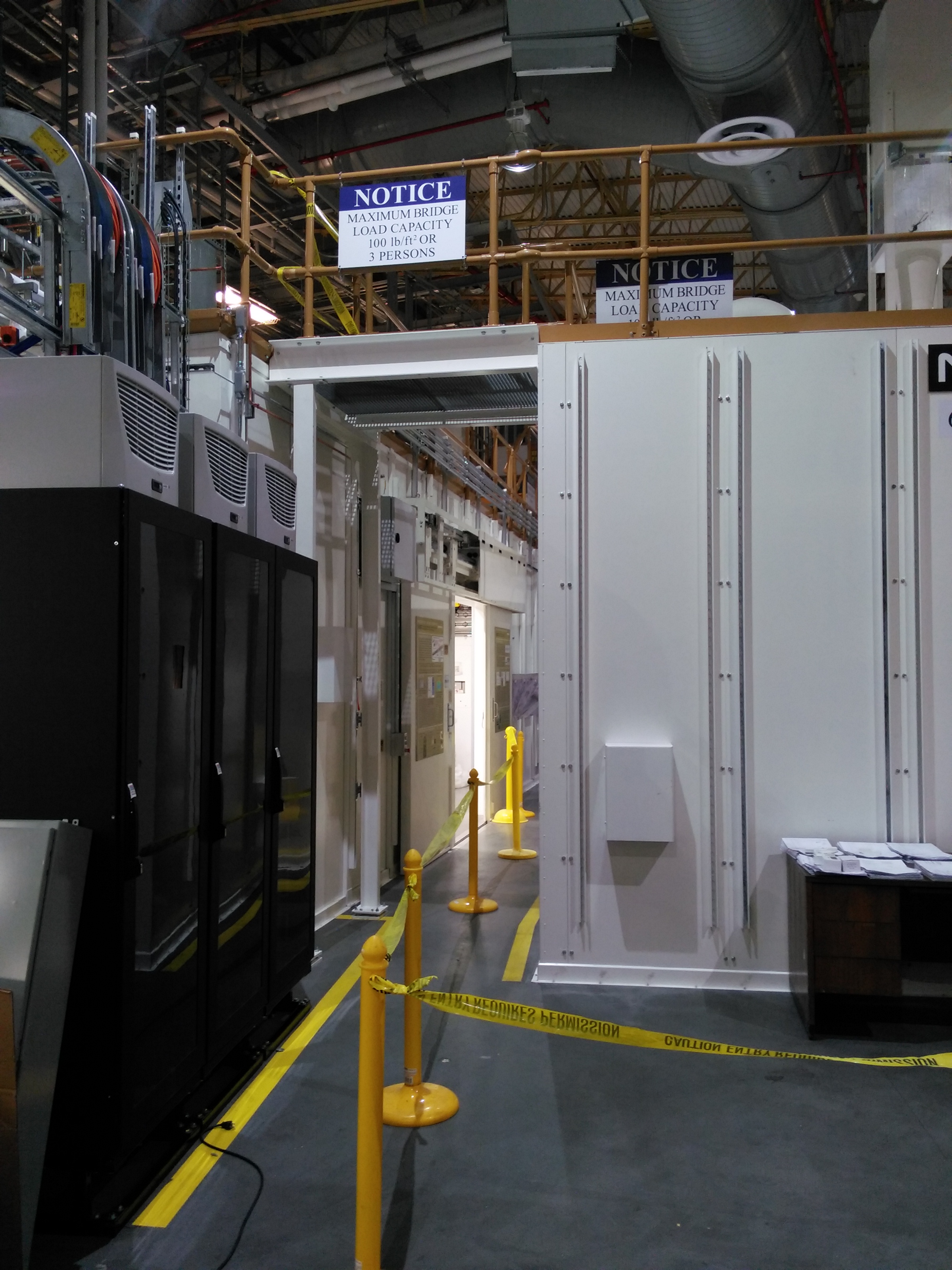
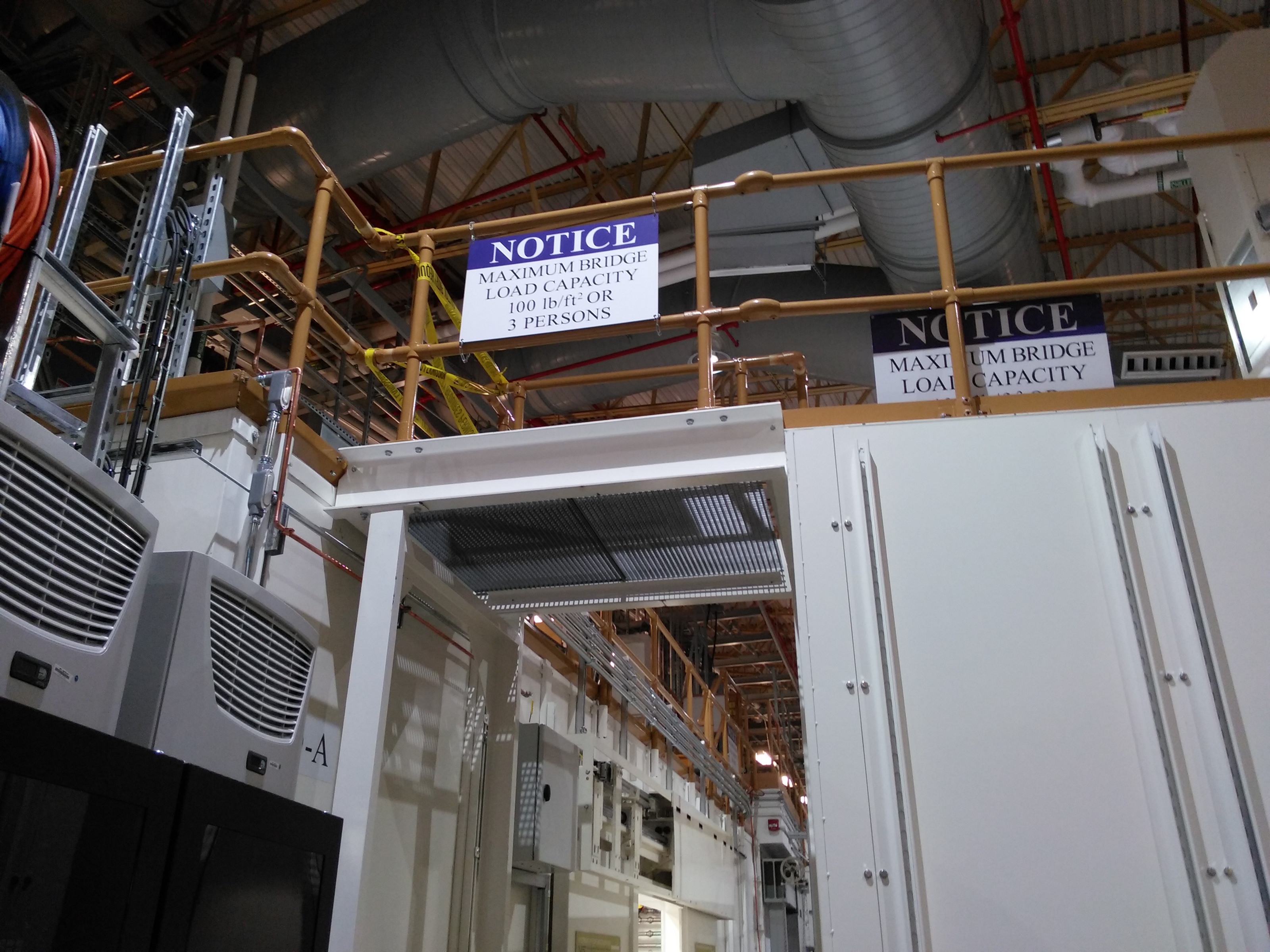
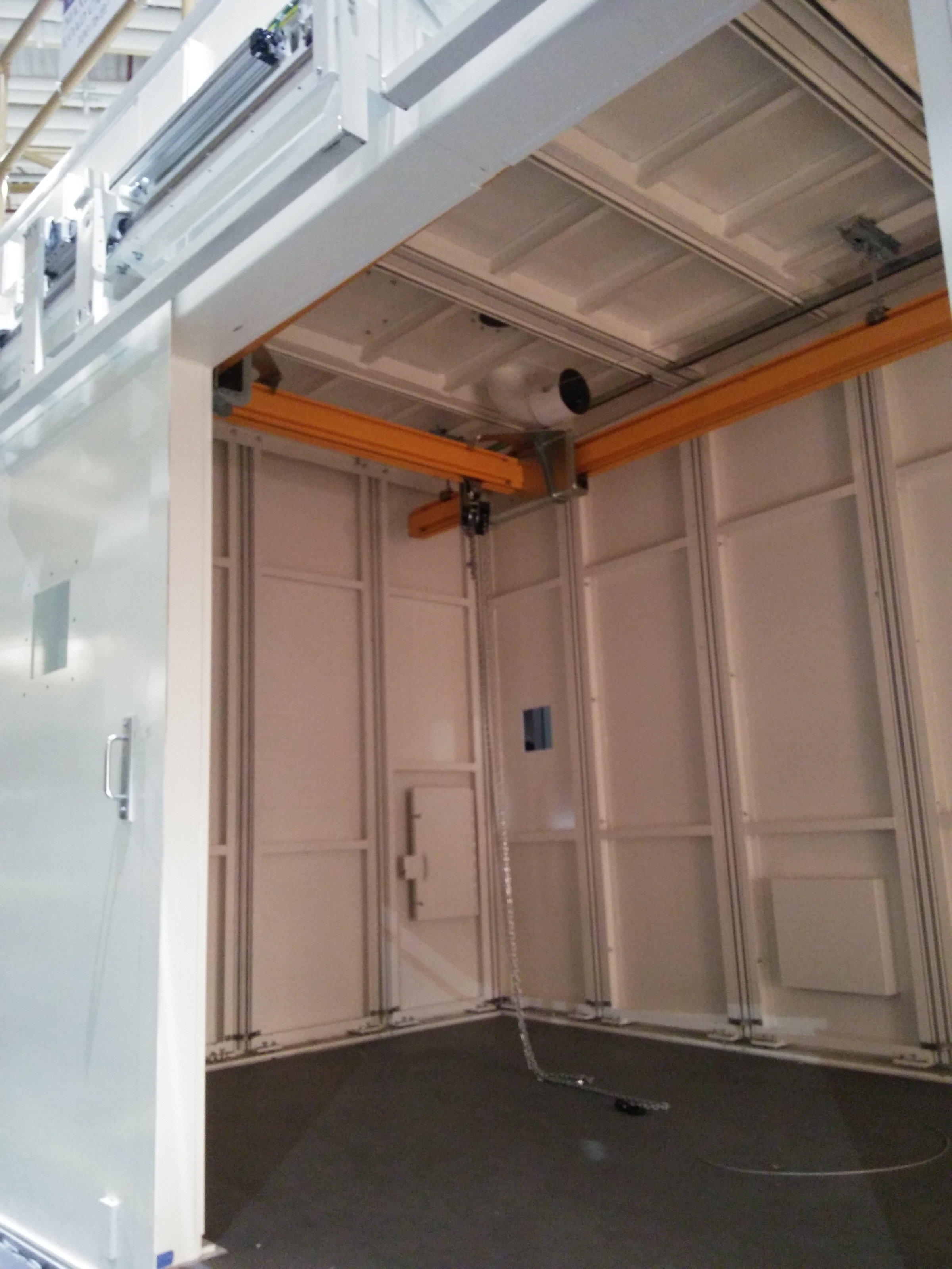
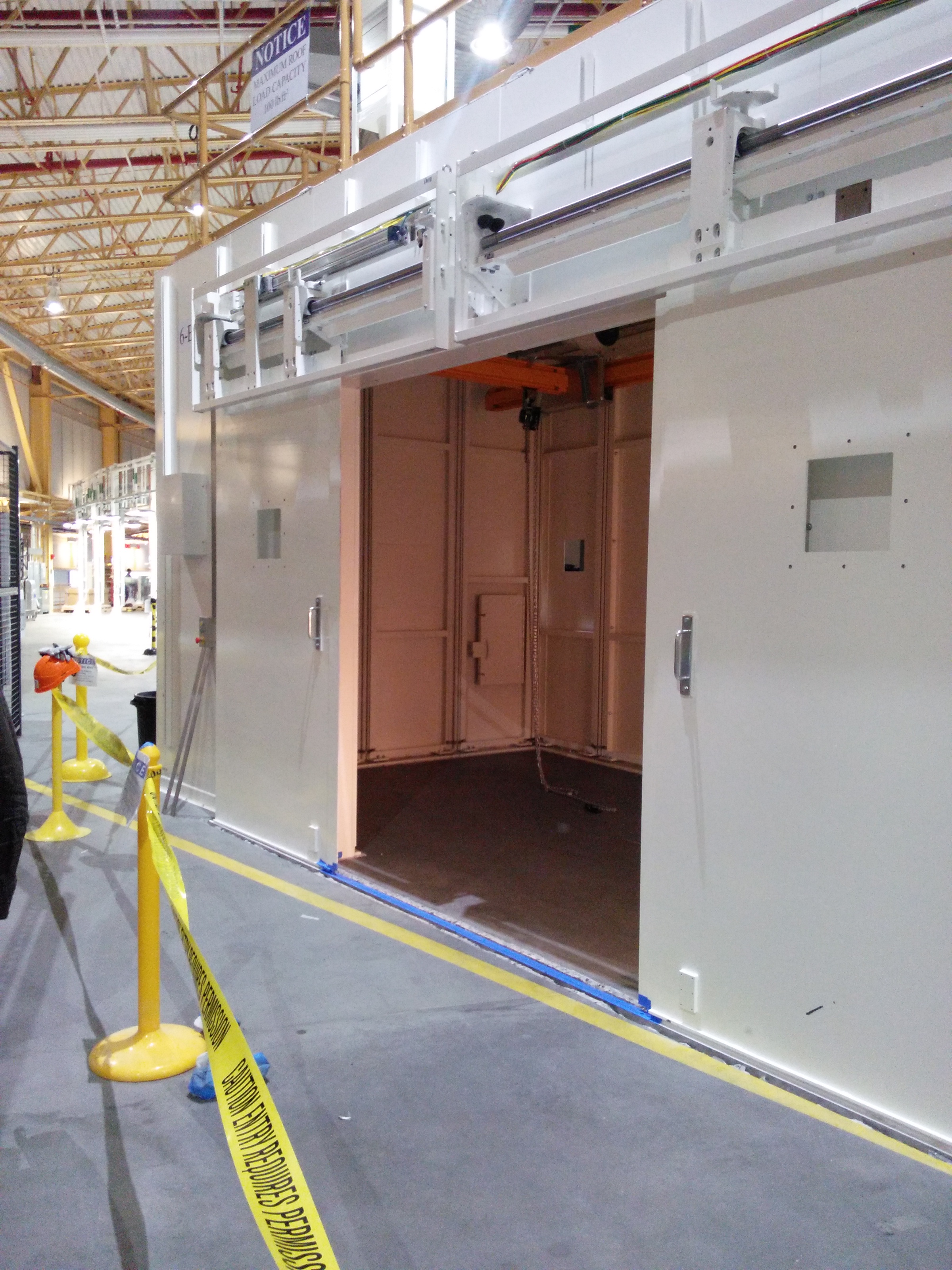
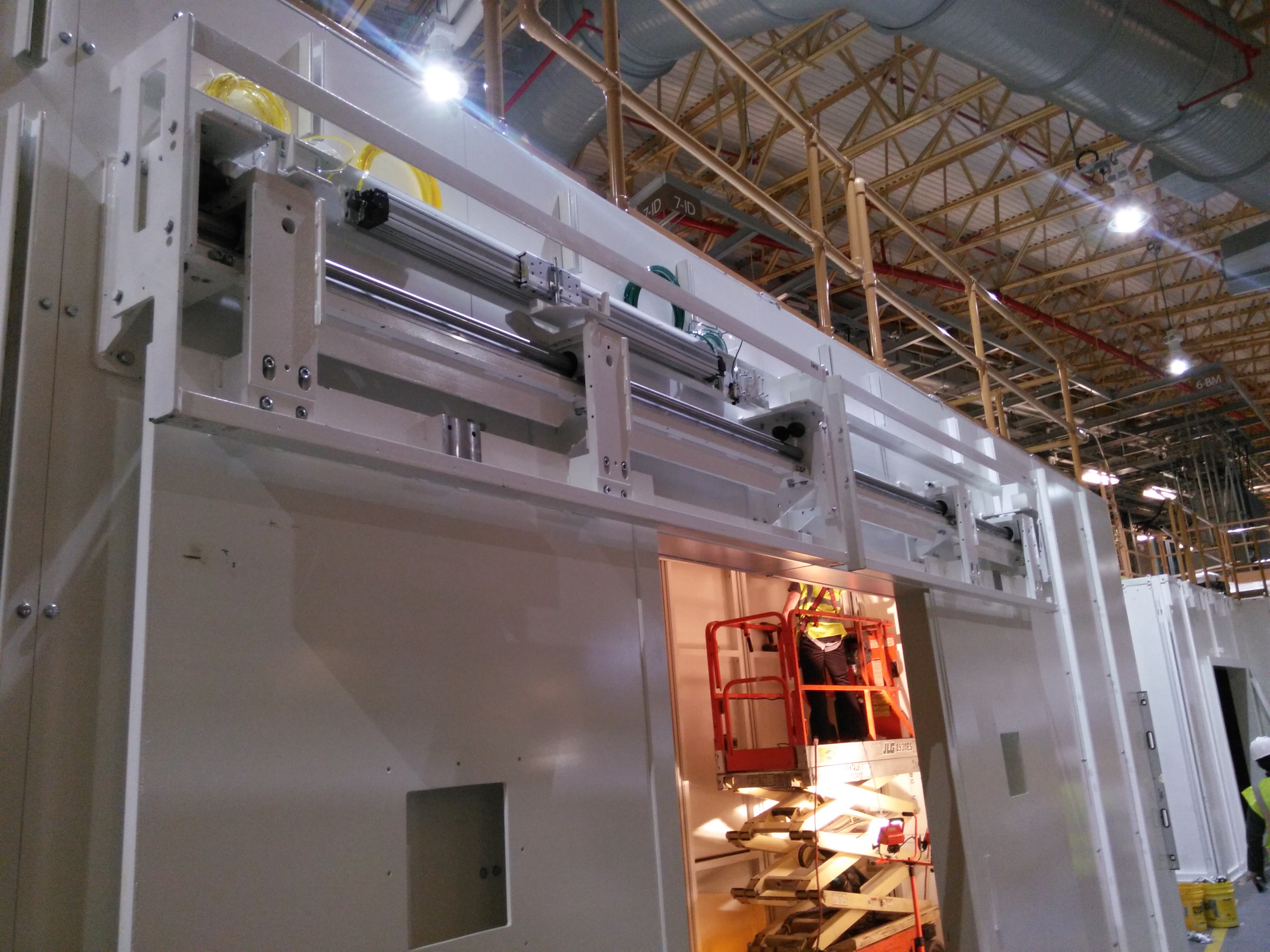
December 14, 2015
Over the weekend, progress was made on several details, including the bridge to 7ID-A, the small staircase to the mezzanine on 6BM-A, and the hoist in 6BM-B.
| Bridge to 7ID-D | Another view of the bridge | The 6BM-B hoist | View of hoist from outside 6BM-B | Small staircase to mezzanine |
 |
 |
 |
 |
 |
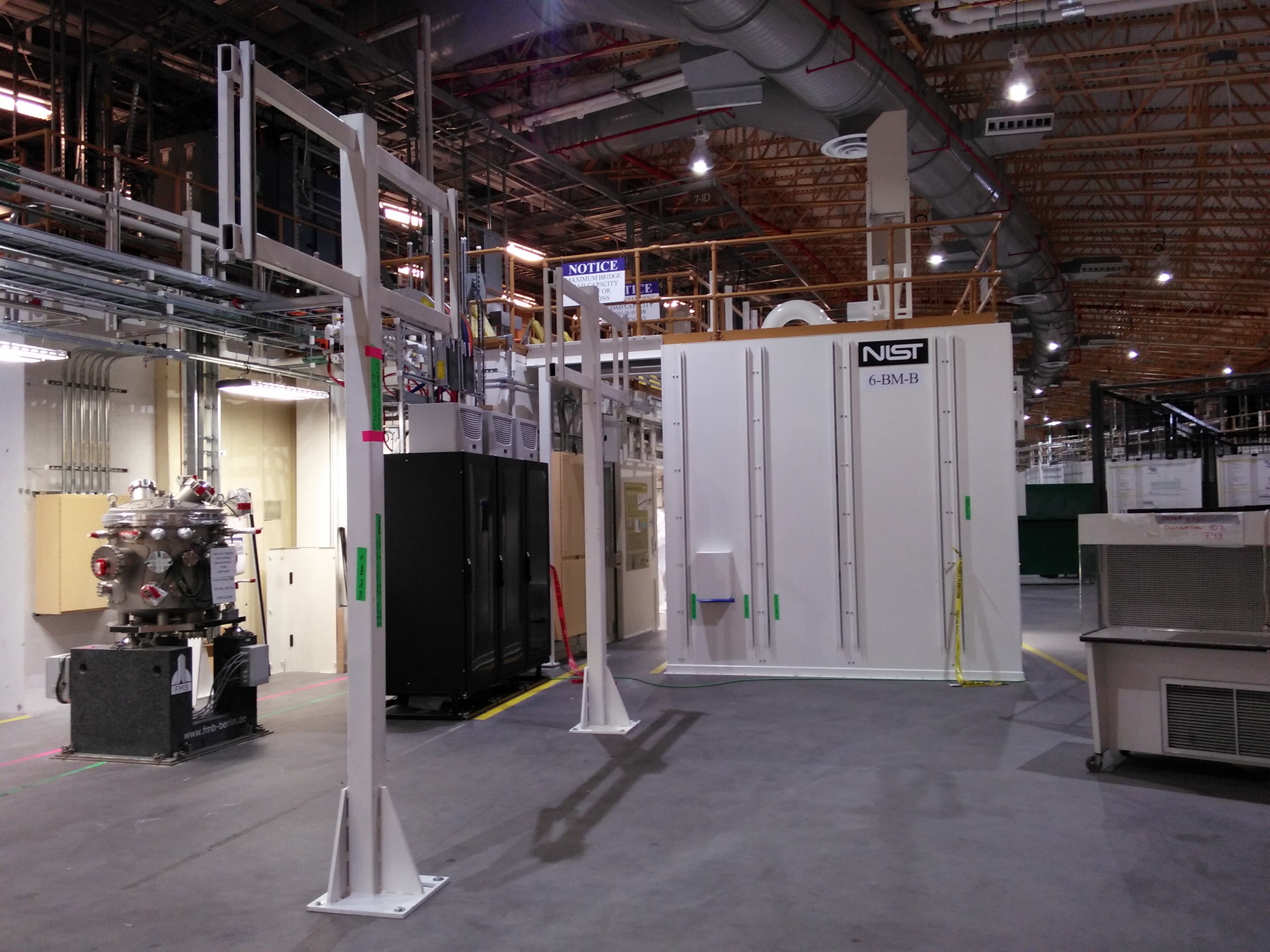
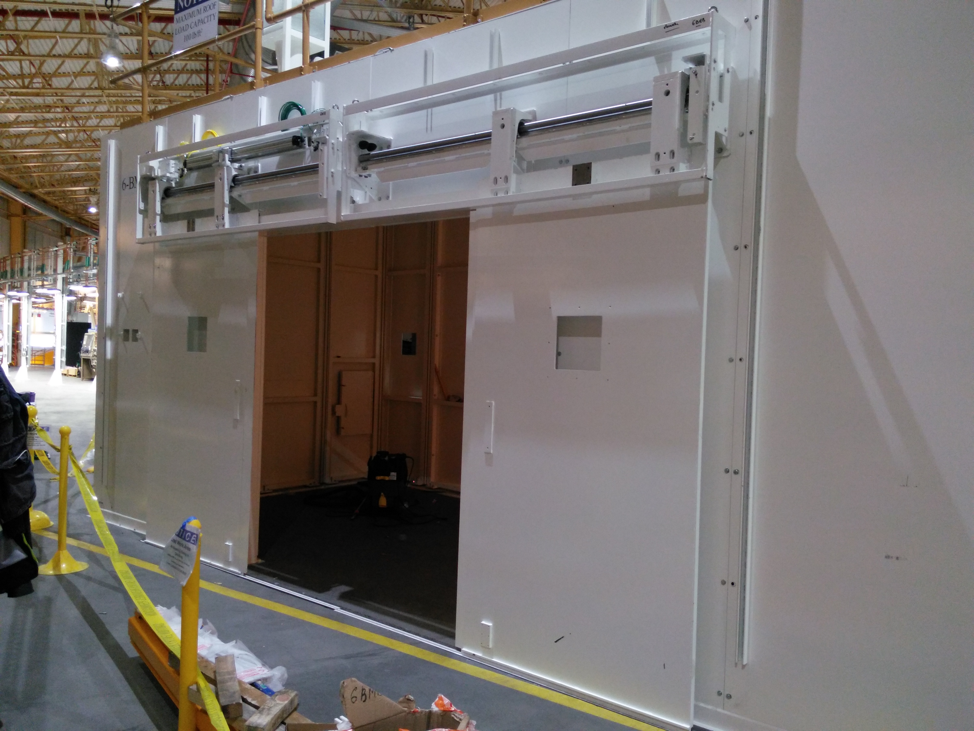
December 8, 2015
Views from the roof of 5ID-D
| View from the roof of 5ID-D | Staircase + 6BM-A door component |
 |
 |
Floor level views of the hutches
| 6BM-B doorway | 6BM-A, view from dowstream | 6BM-A, view from the side | Detail of 6BM-B door |
 |
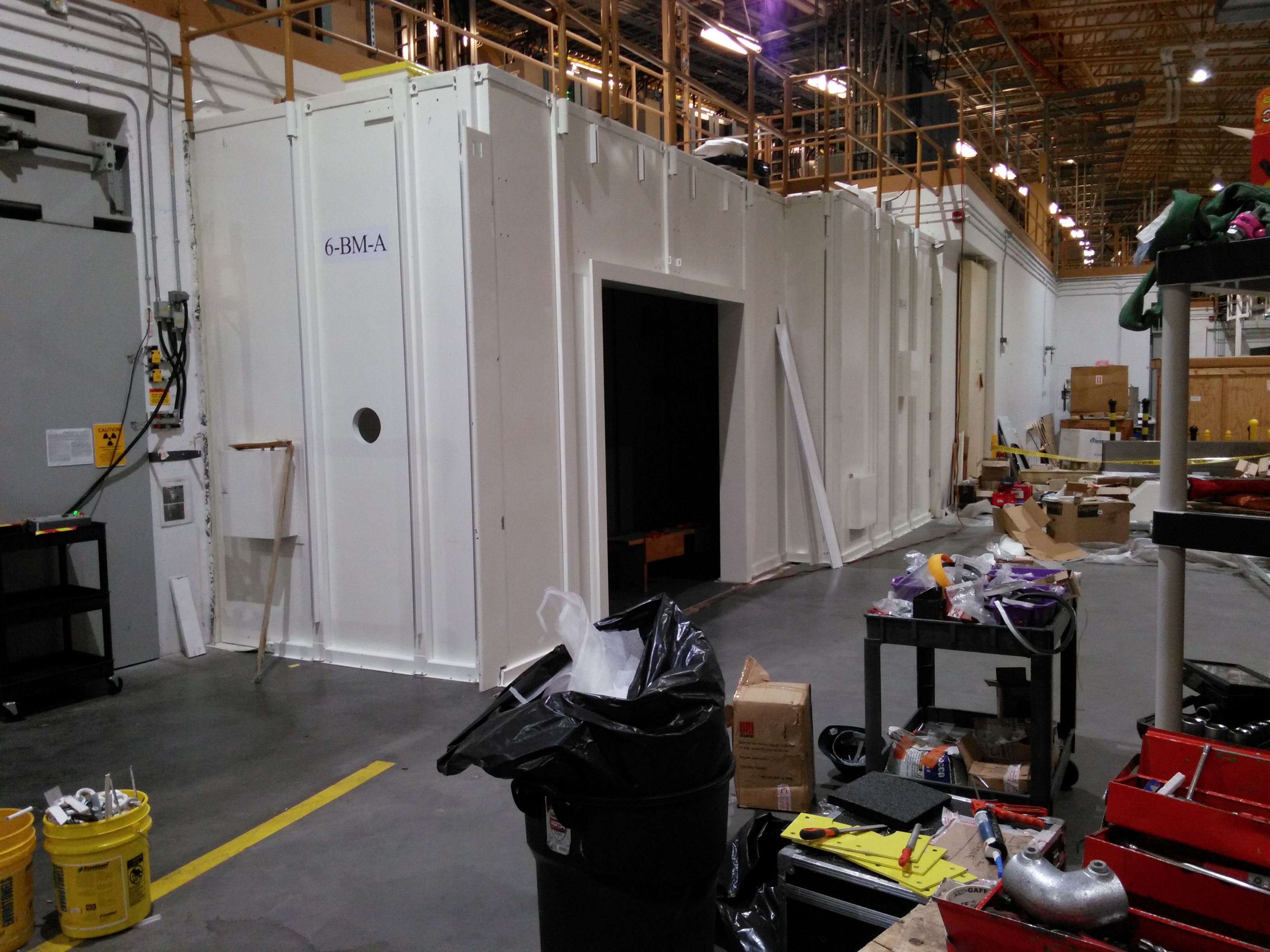 |
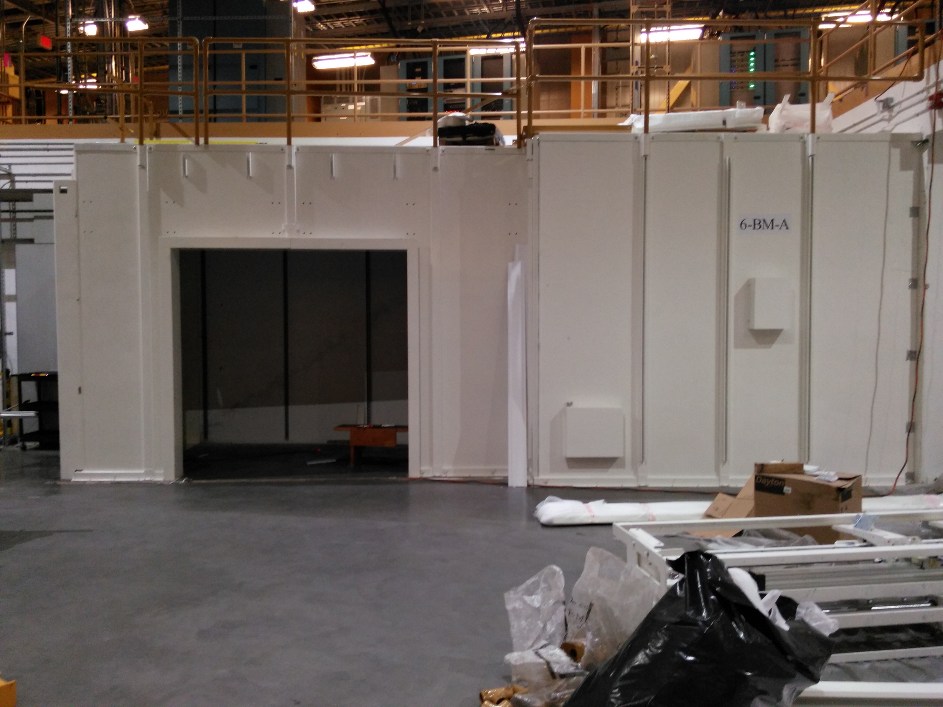 |
 |
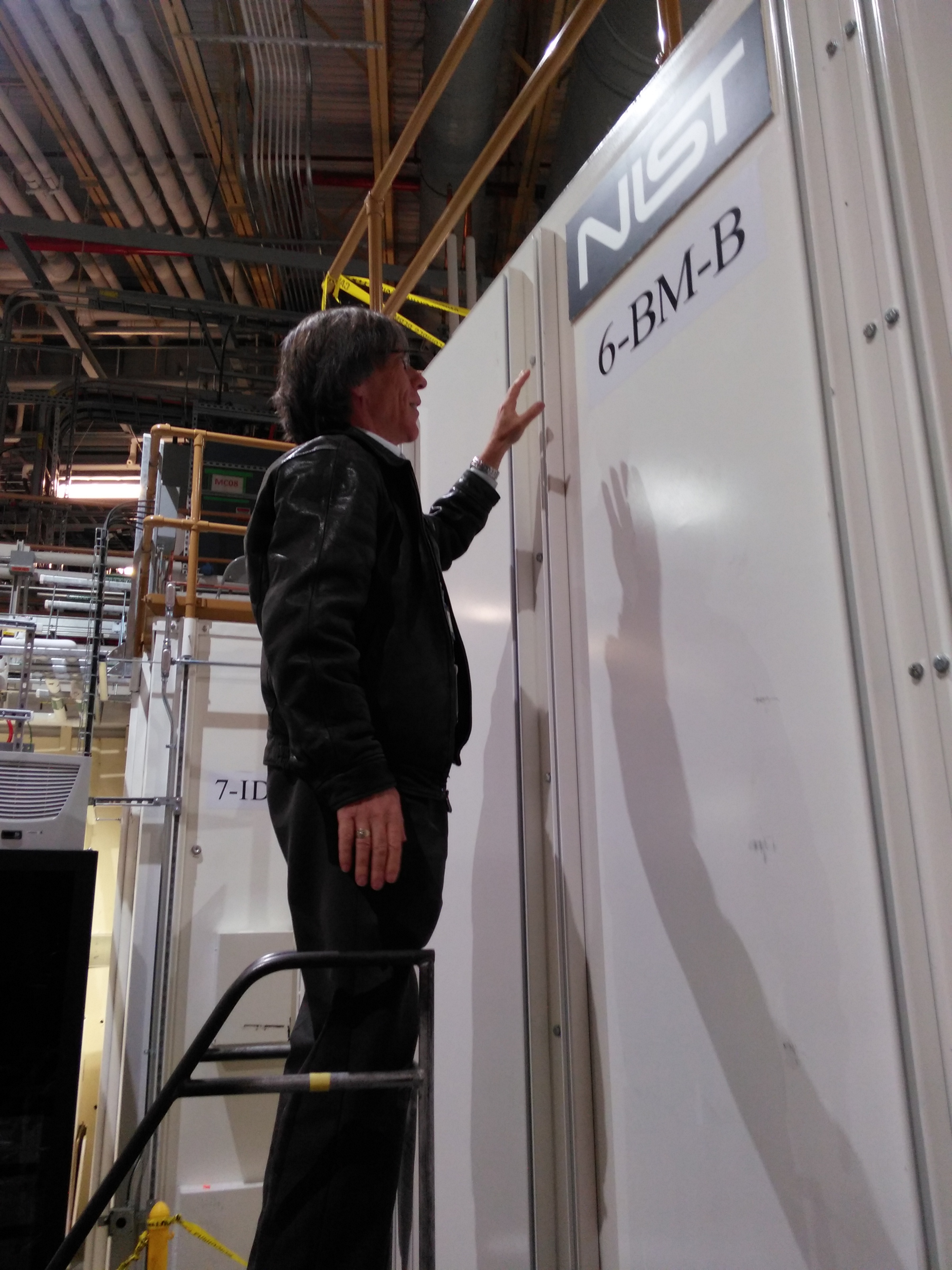
Branding is key!
| Dan says "Let's brand this thing!" | Branding accomplished! |
 |
 |
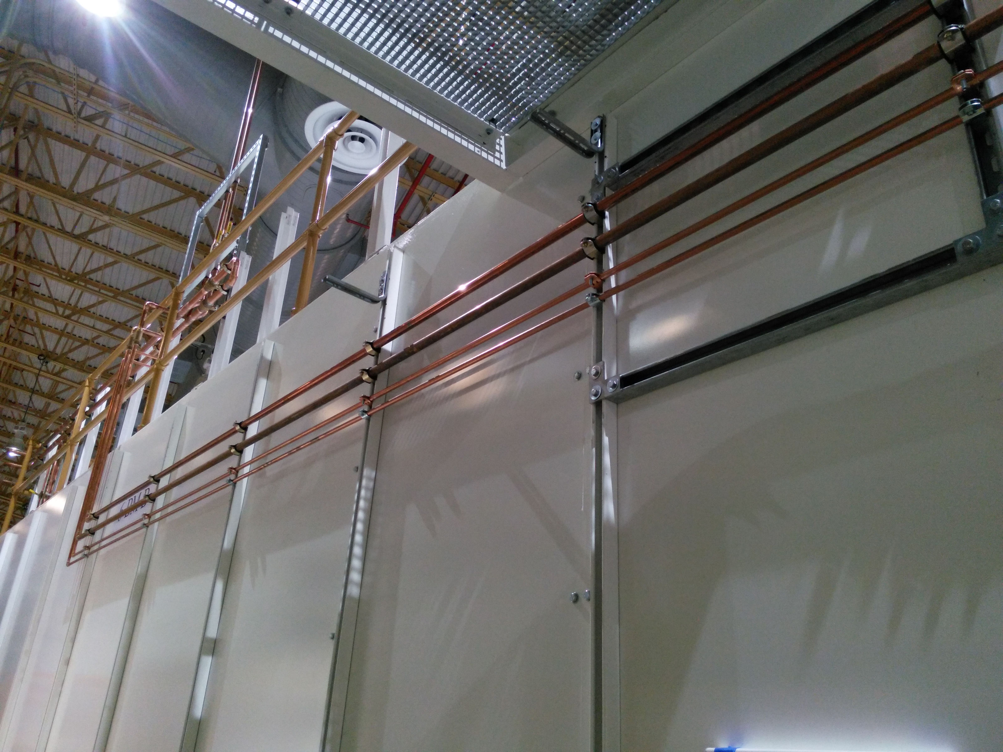
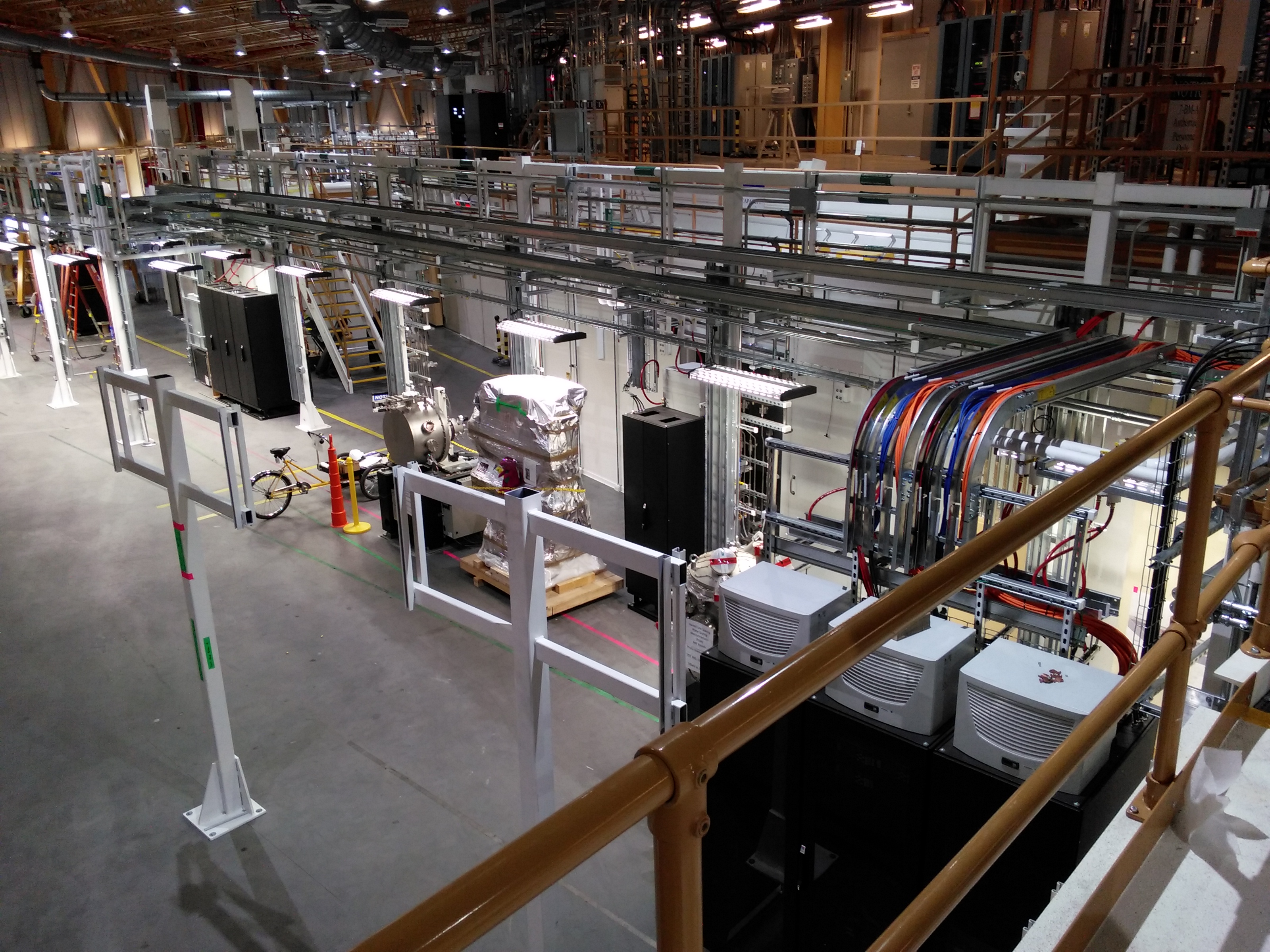
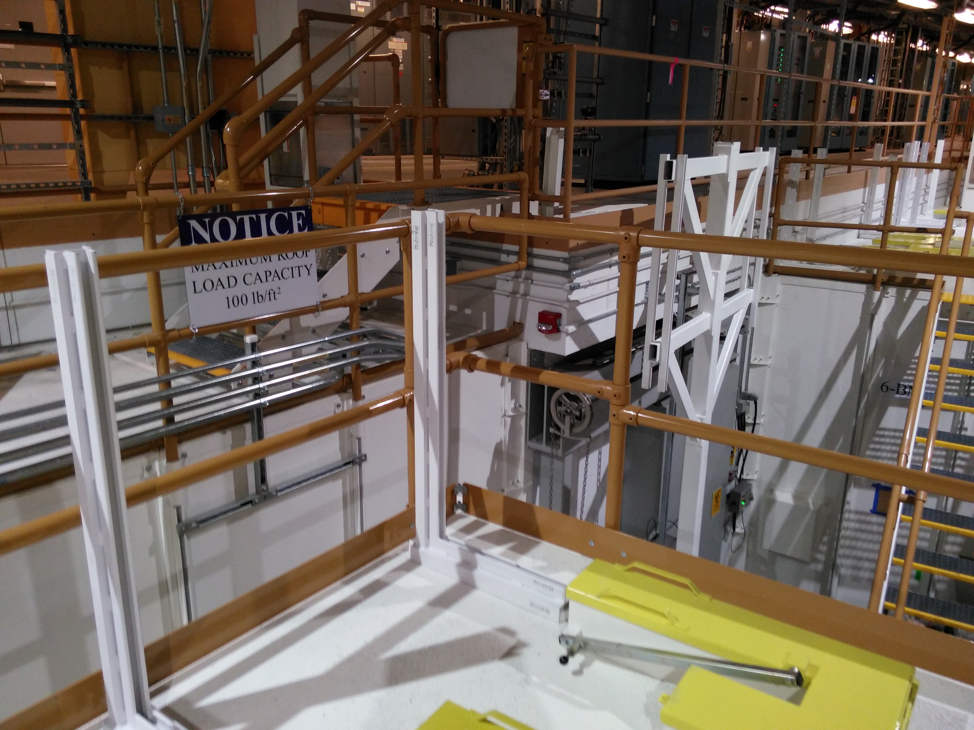
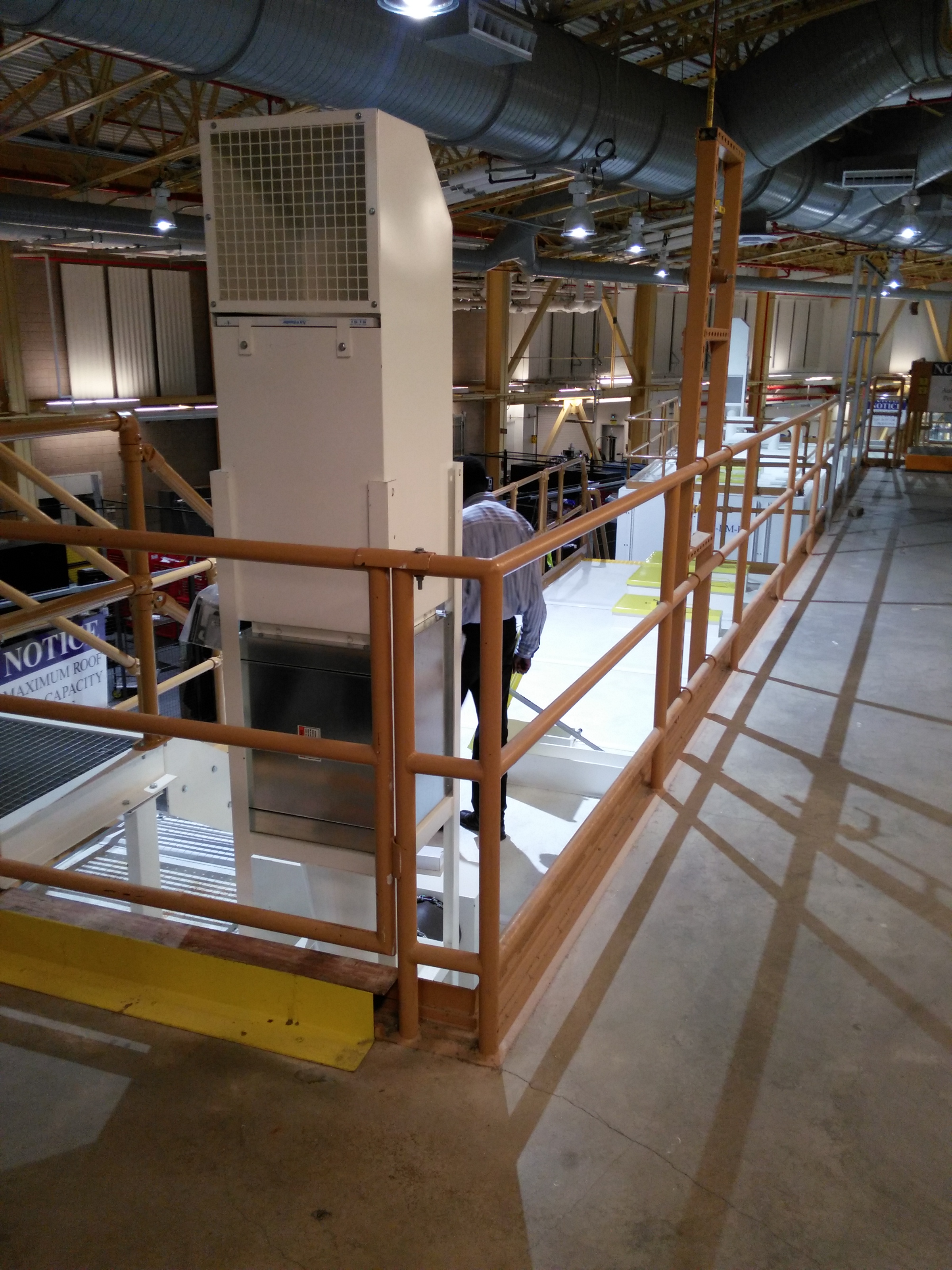
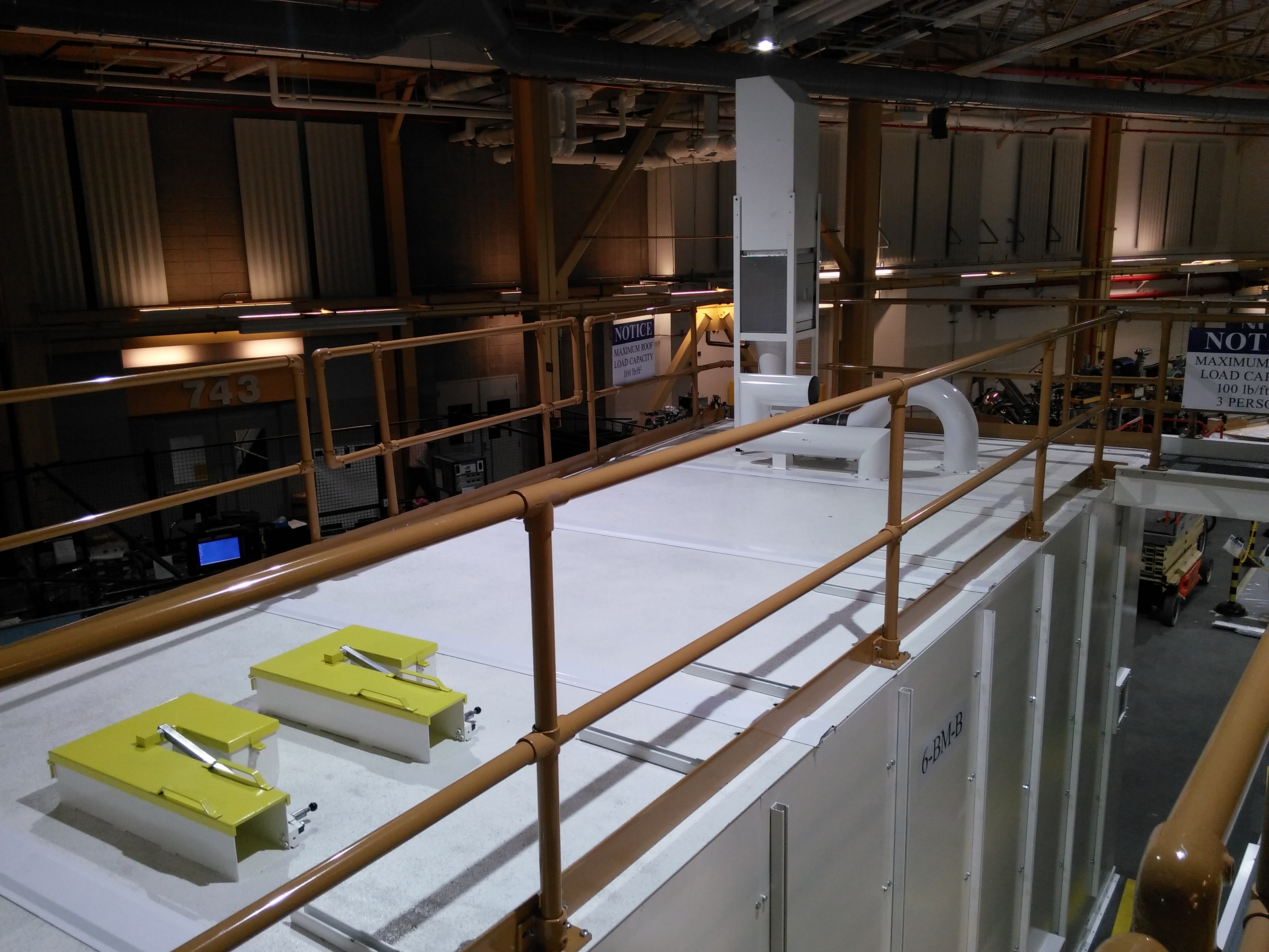
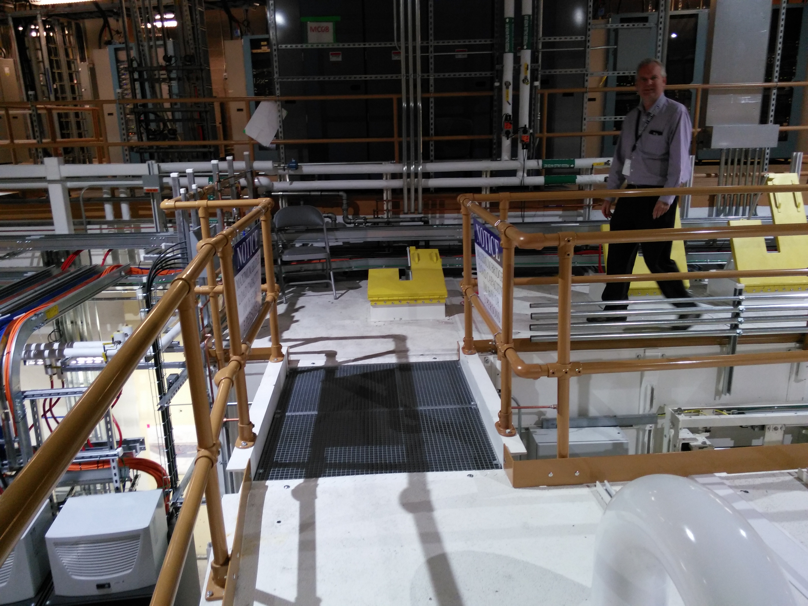
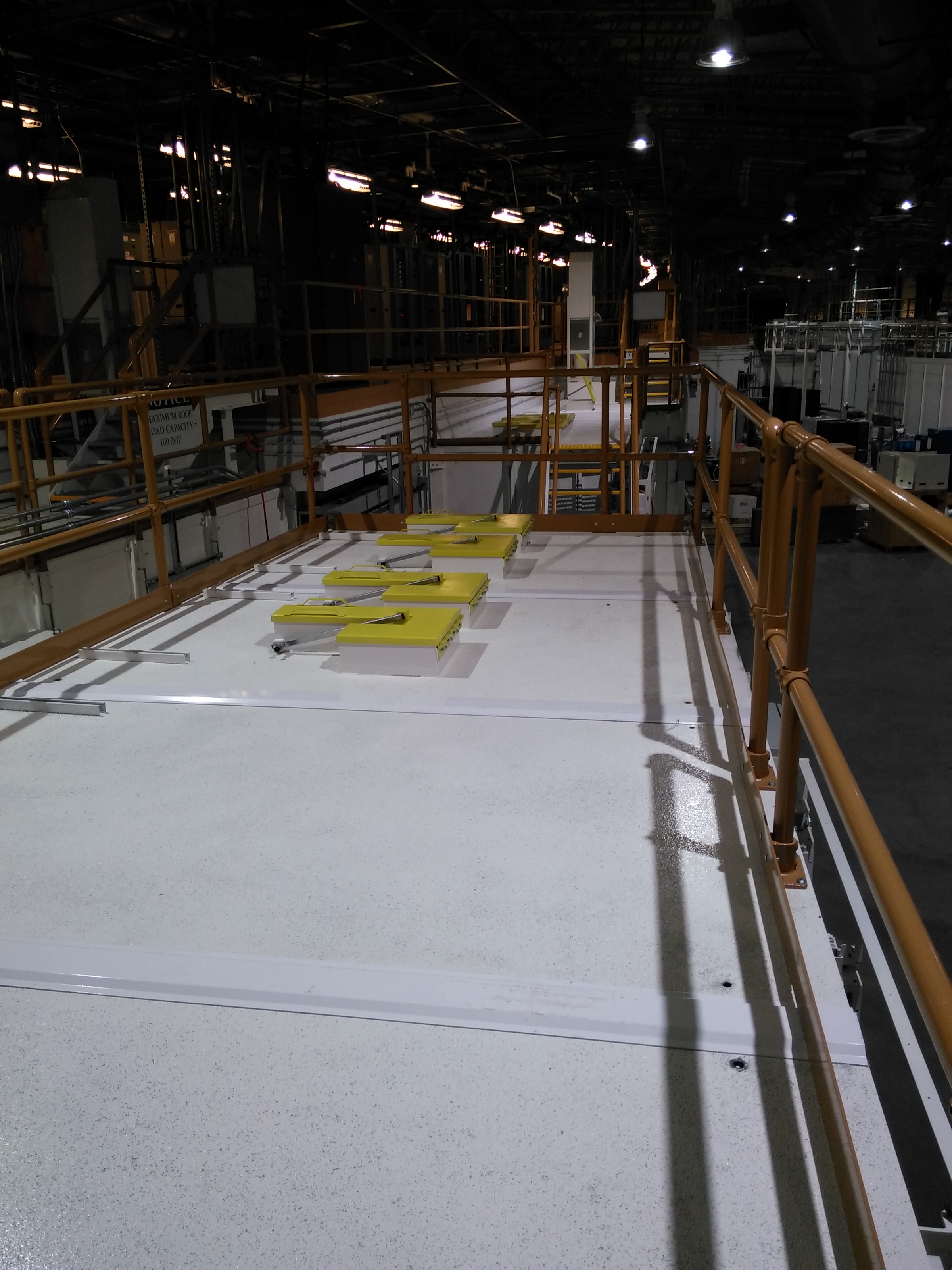
Views from the mezzanine
| Looking down the length of 6BM | 6BM-A roof | 6BM-B roof | View of 6BM-A from the roof of 7ID-A | 6BM-B labyrinths | 6BM-B air handling | Looking up the length of 6BM from 7ID-A |
 |
 |
 |
 |
 |
 |
 |
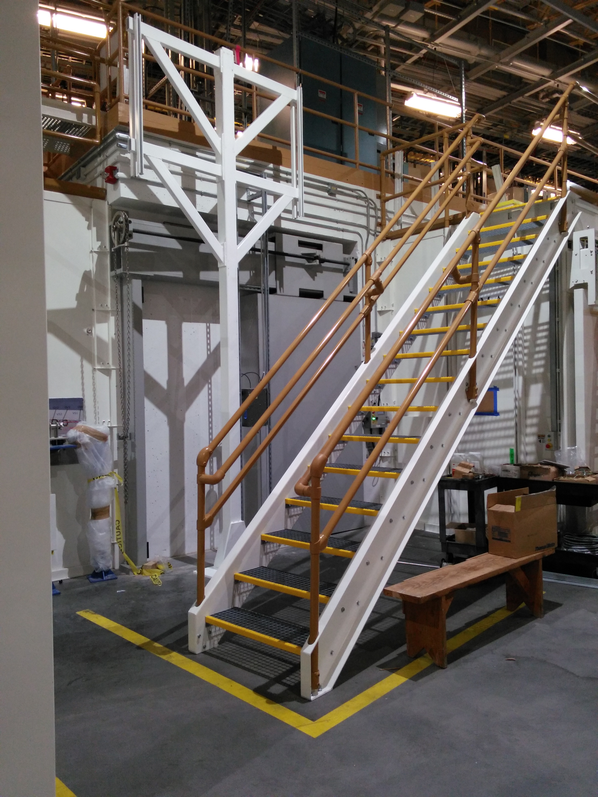
December 2, 2015
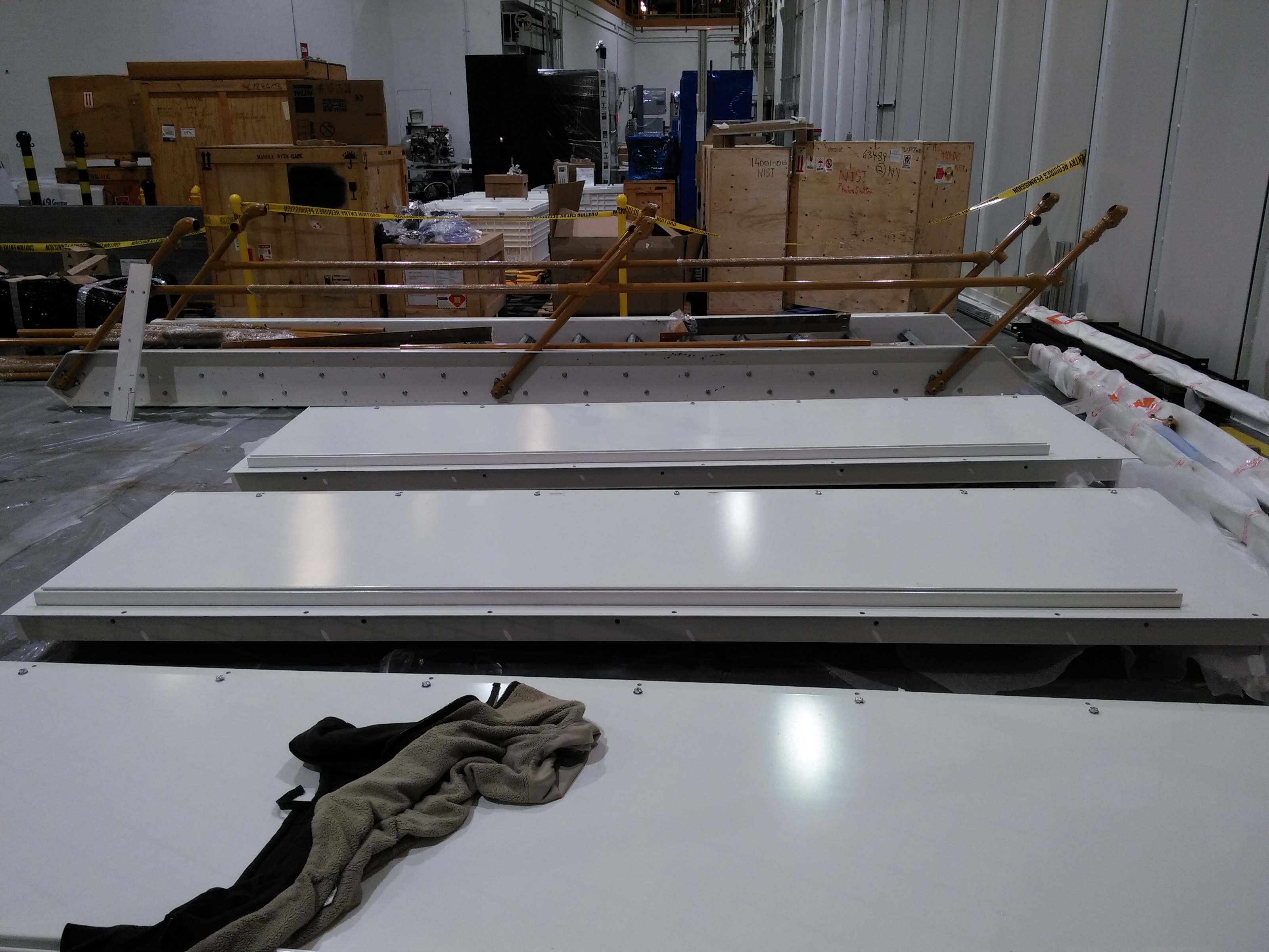
Figure 6: 6BM-A staircase, under construction
December 1, 2015
| Hutch A from downstream | Pieces of the hutch A door | Securing the wall panels to the floor | Wall assembly | A hutch from 5ID-D roof | Lifting ceiling panels | Lifting ceiling panels |
 |
 |
 |
 |
 |
 |
 |
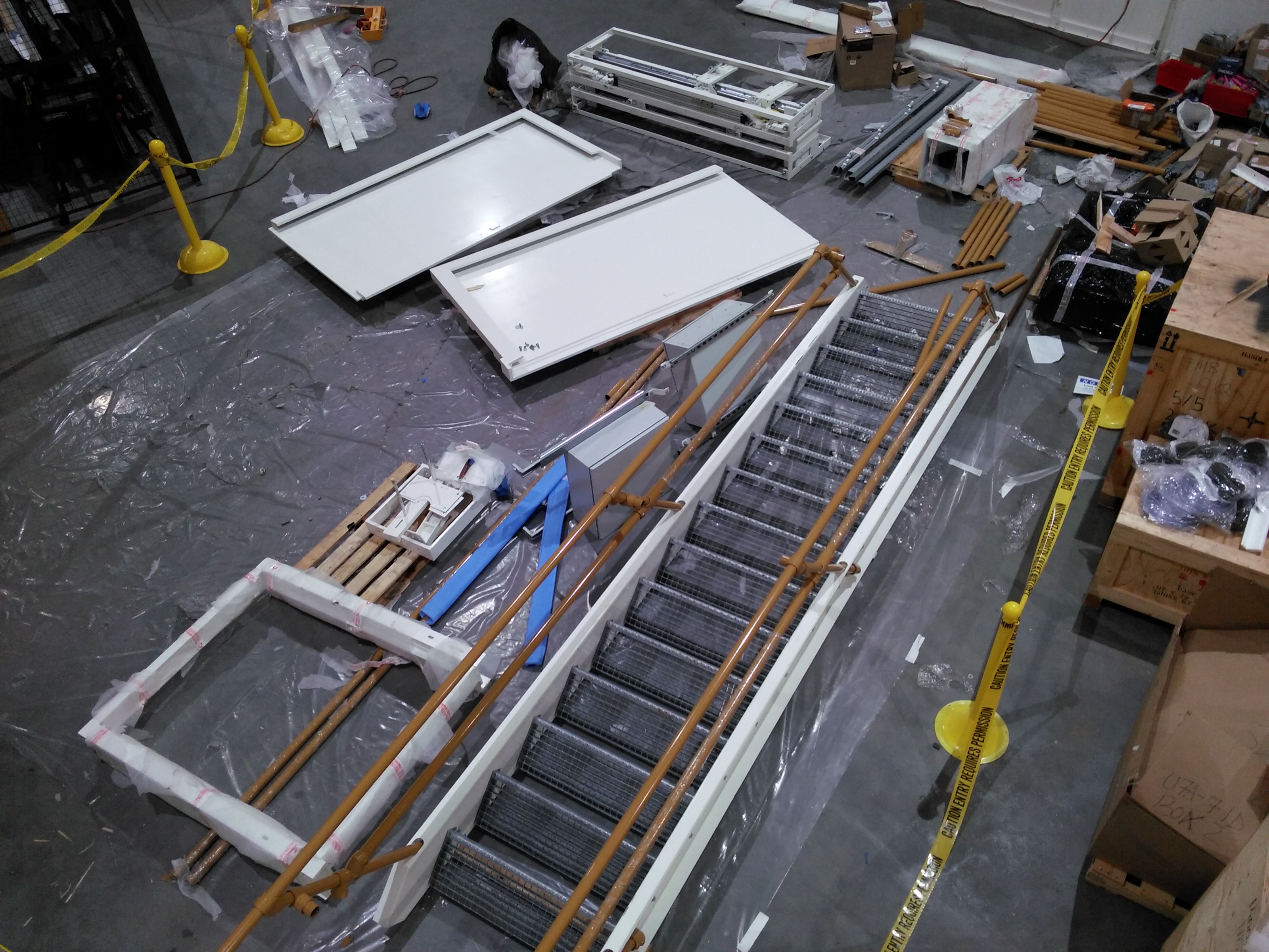
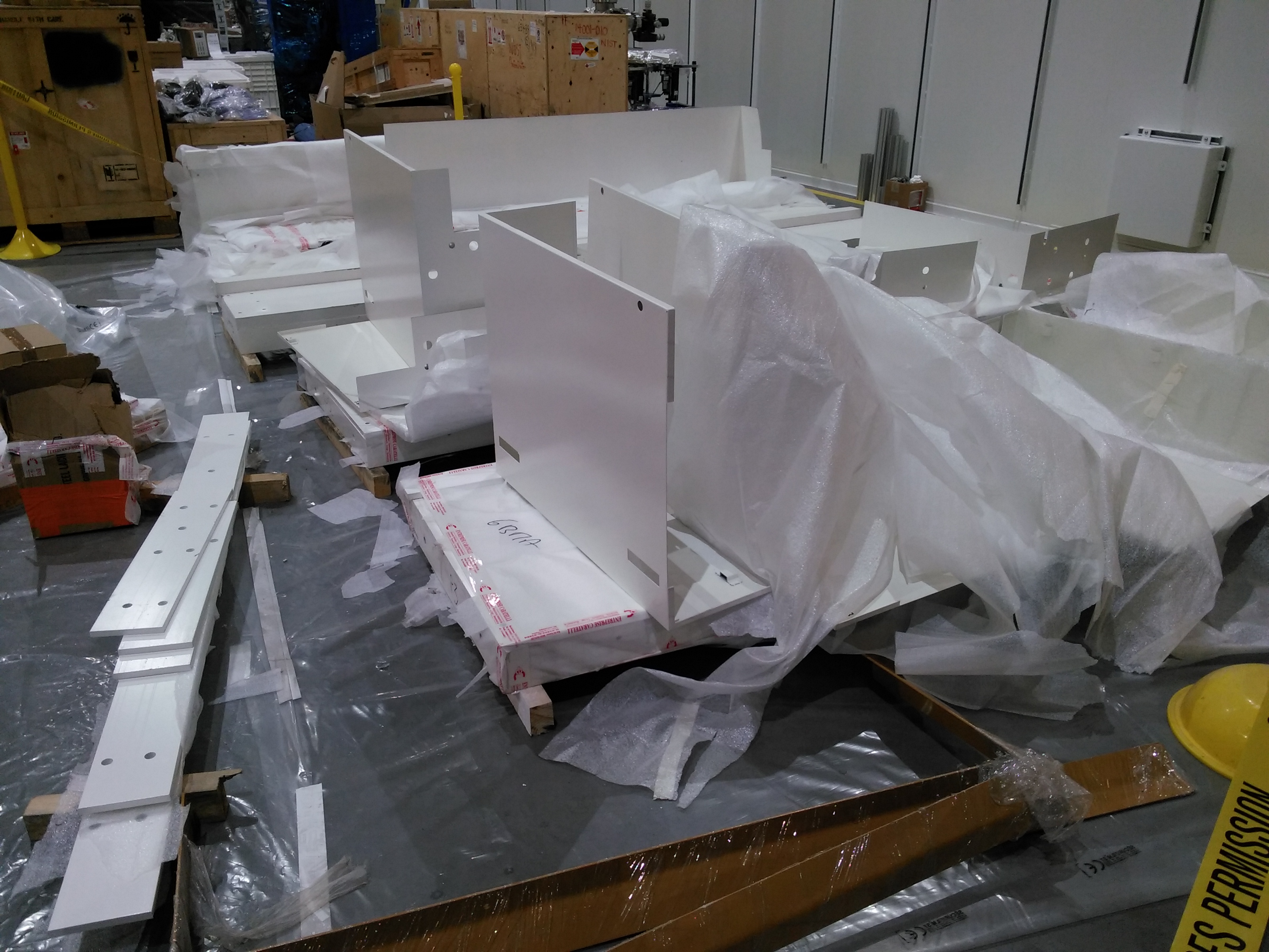
November 23, 2015
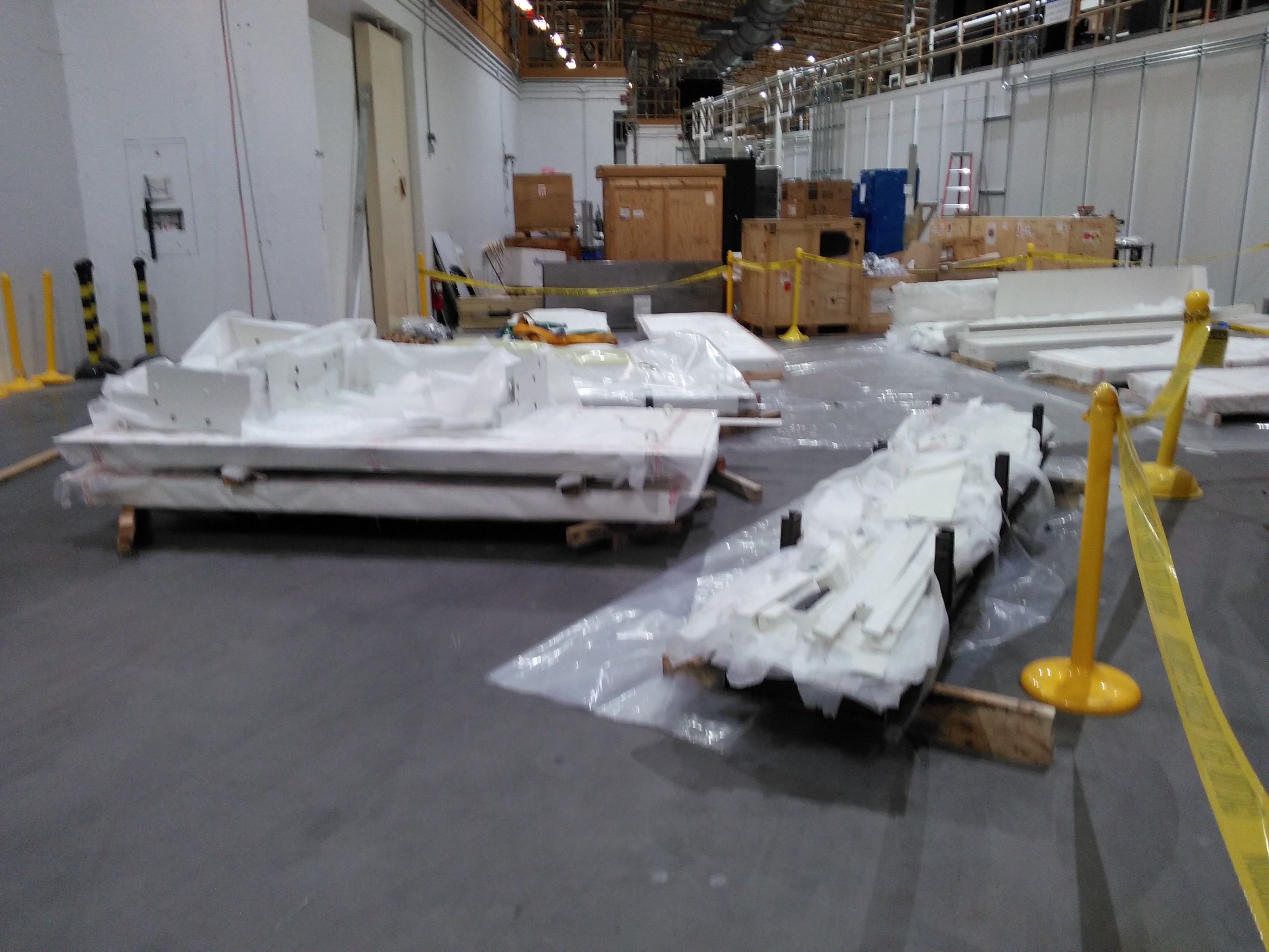
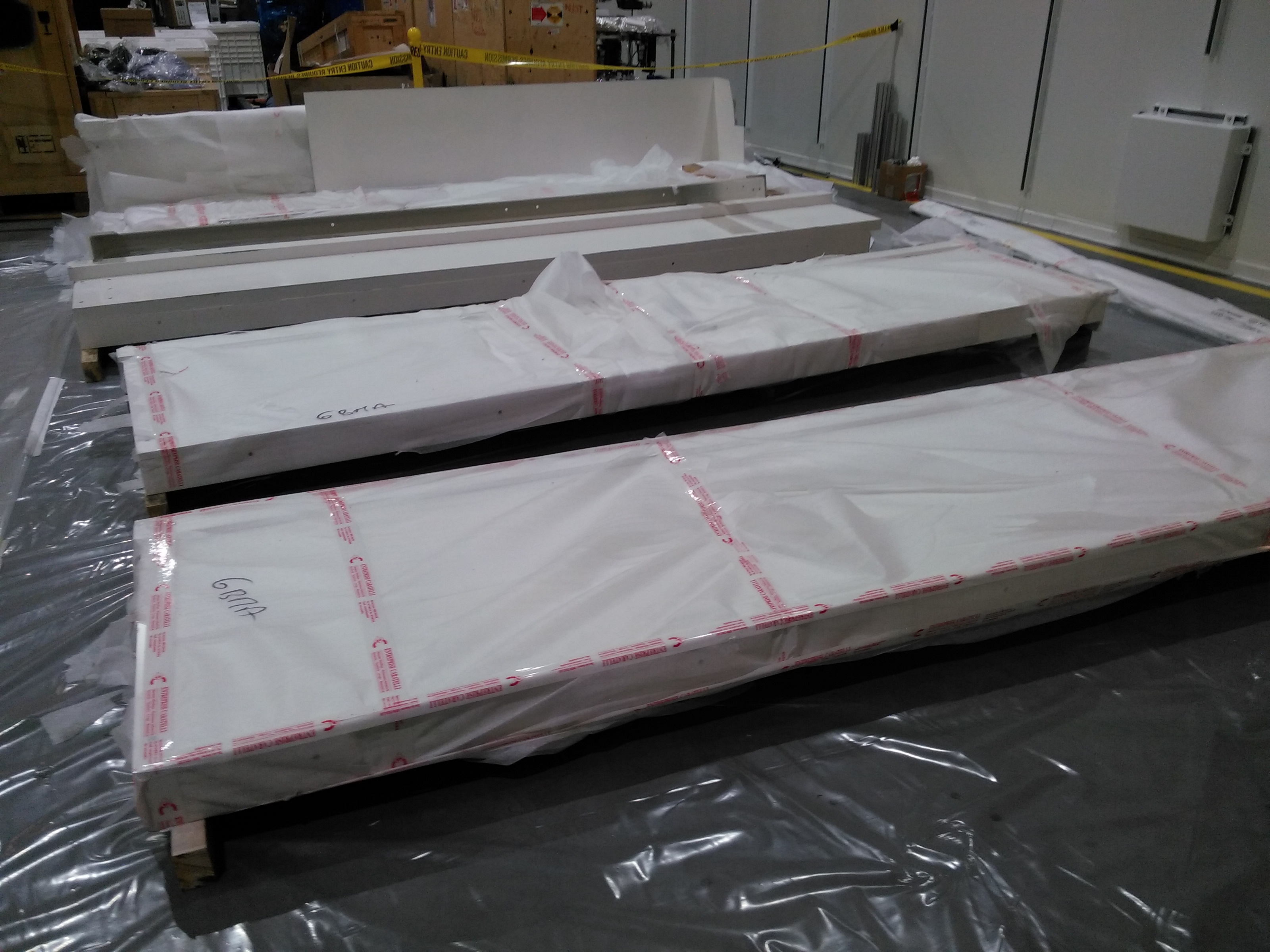
More of our panels have arrived
| Wall pieces | Railing pieces |
 |
 |
November 10, 2015
Hints of things to come: This is the staircase to the 4BM-B roof, assembled yesterday.
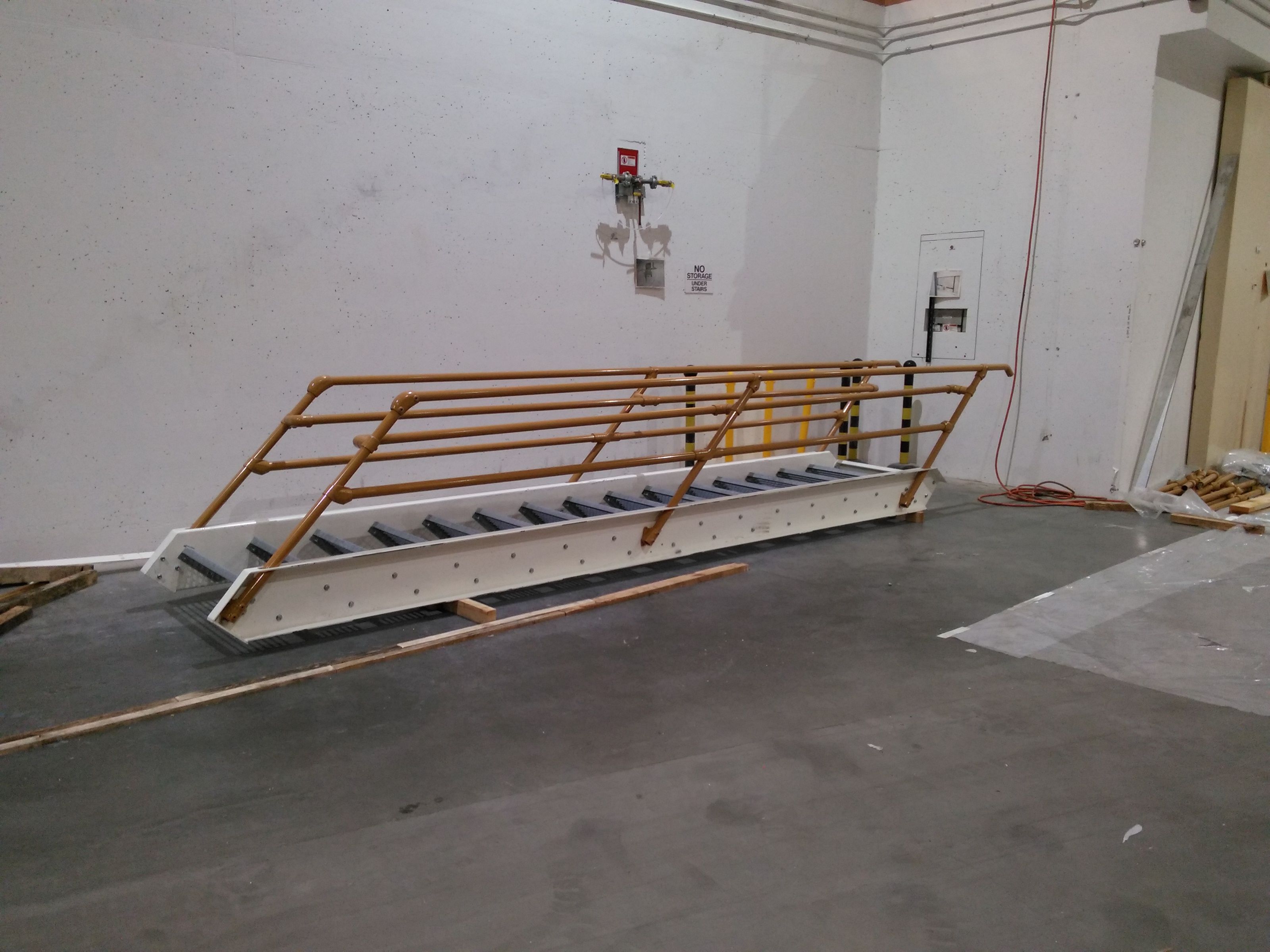
Figure 7: 4BM-A staircase
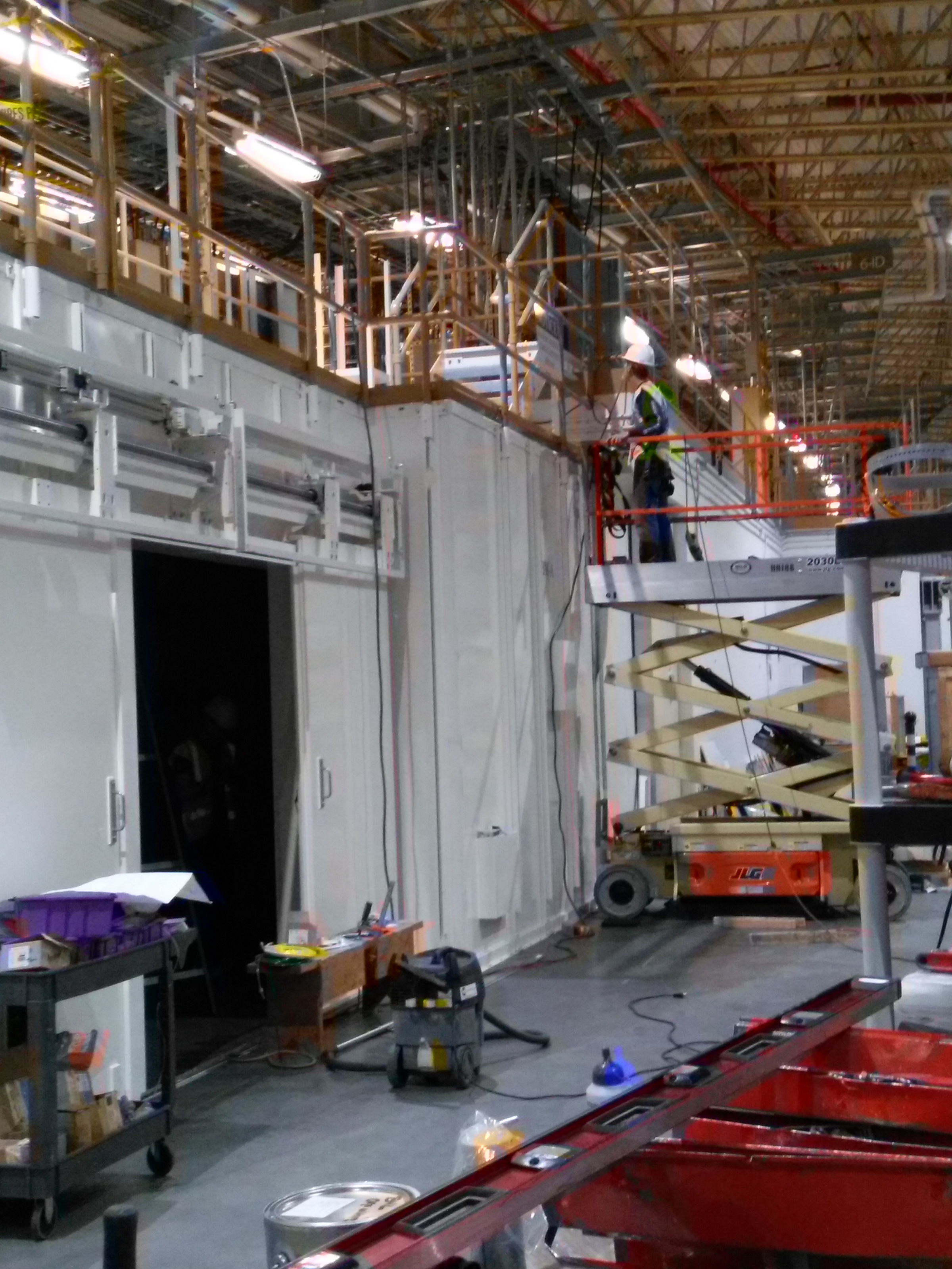
November 9, 2015
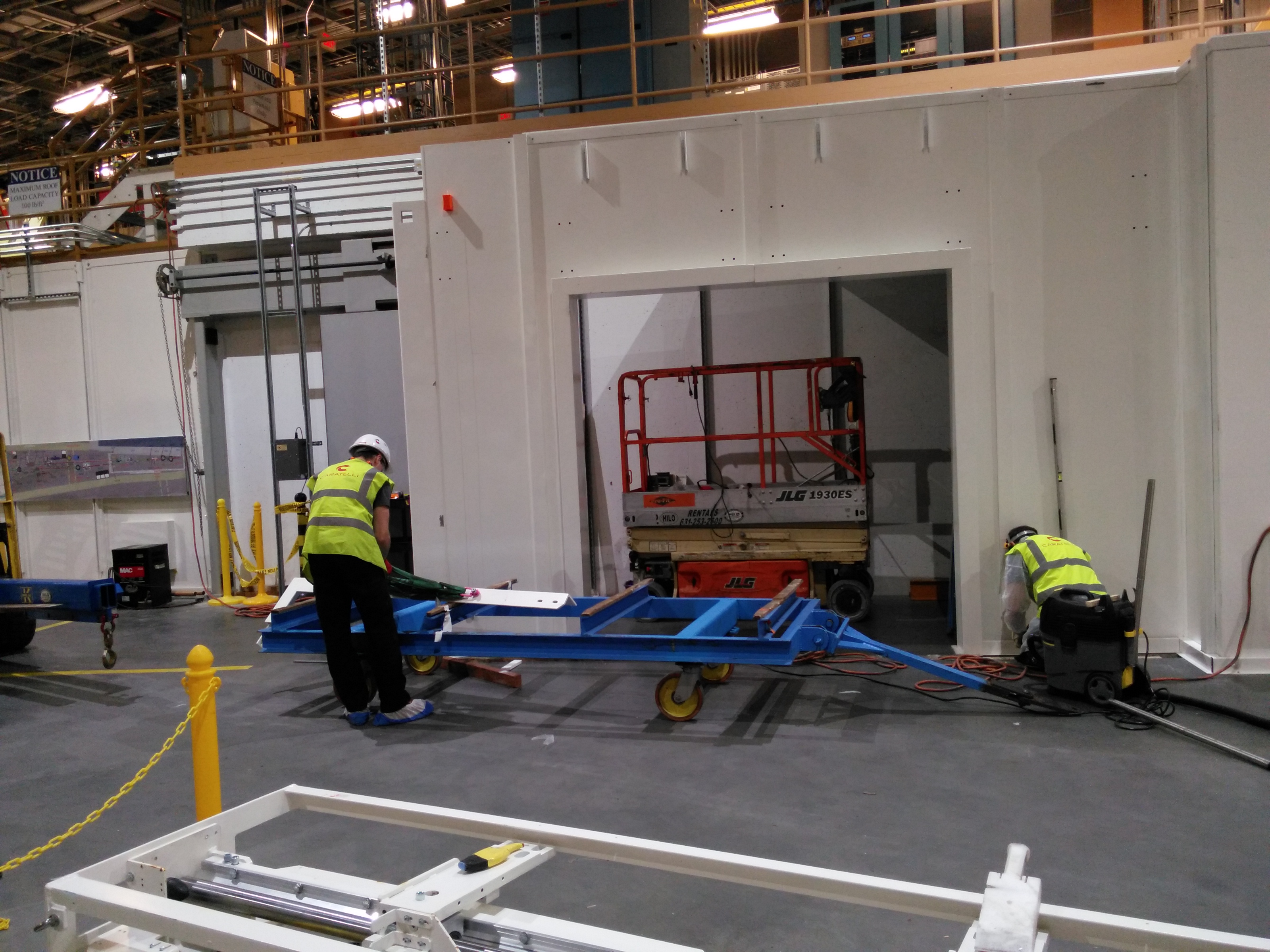
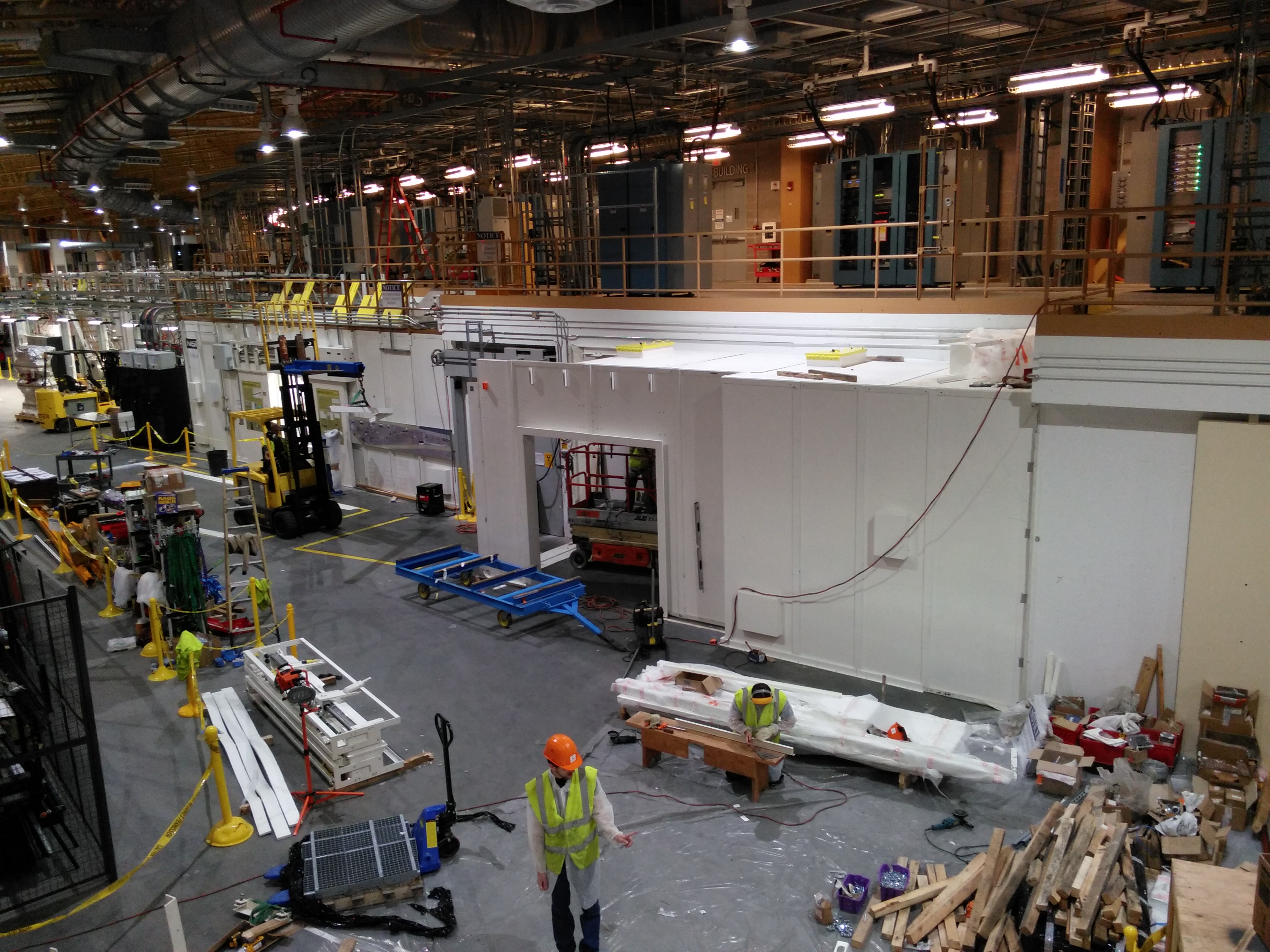
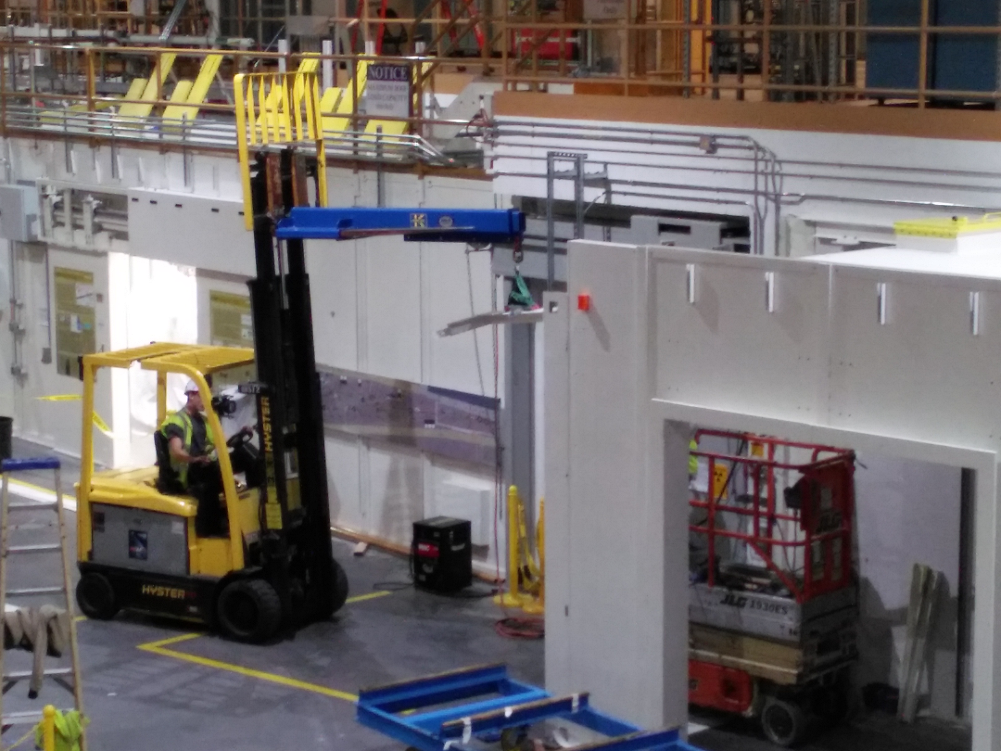
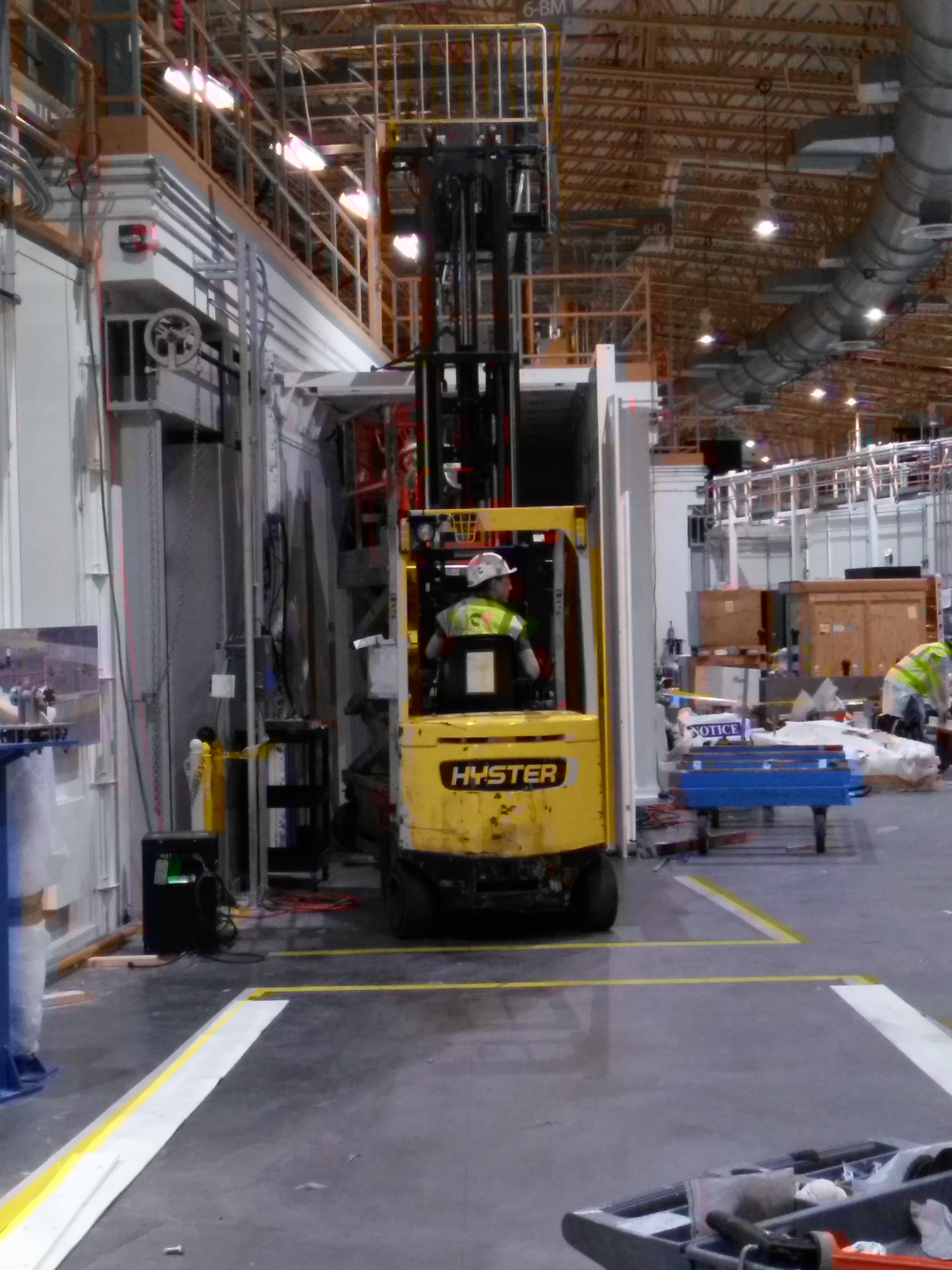
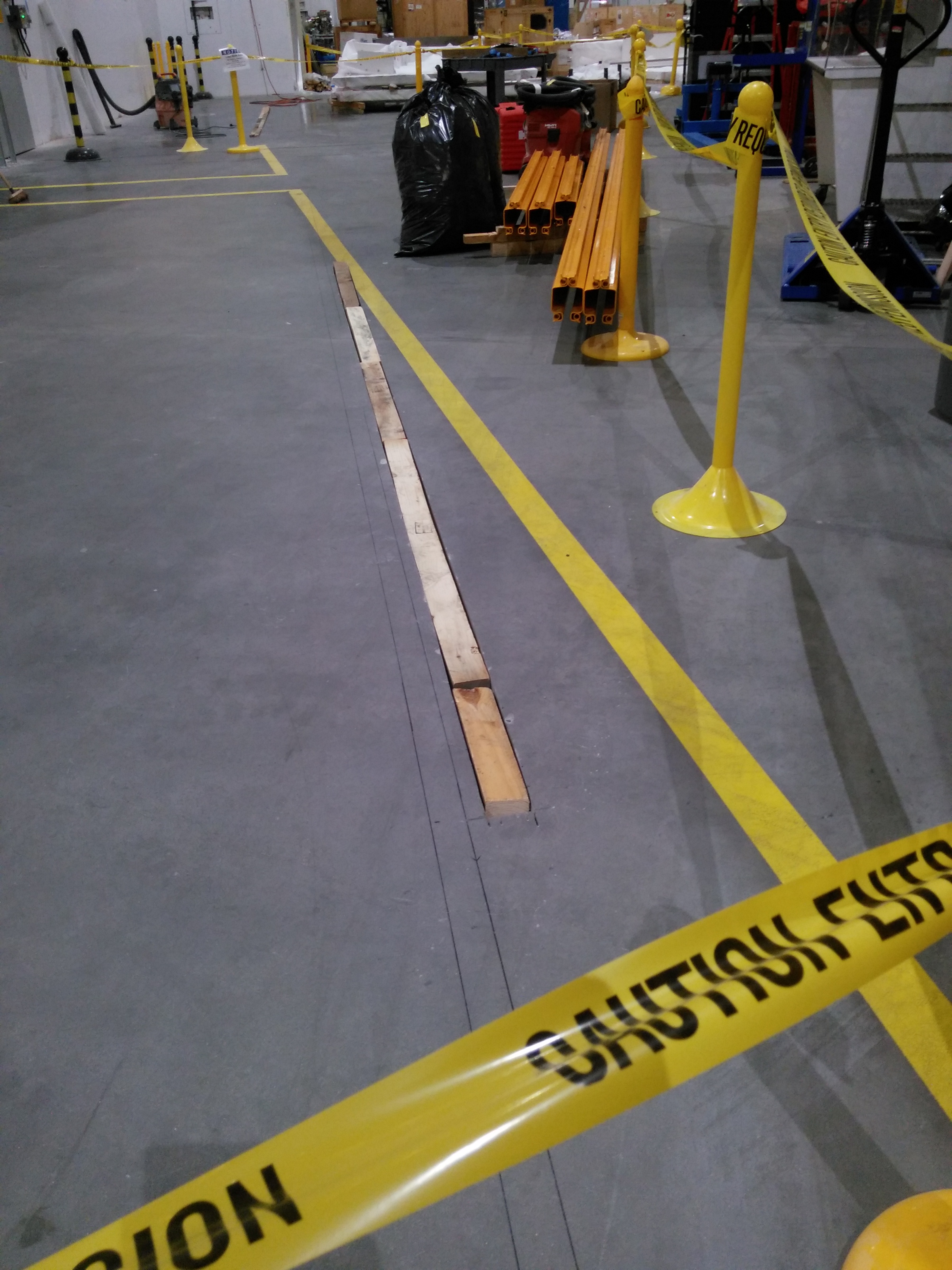
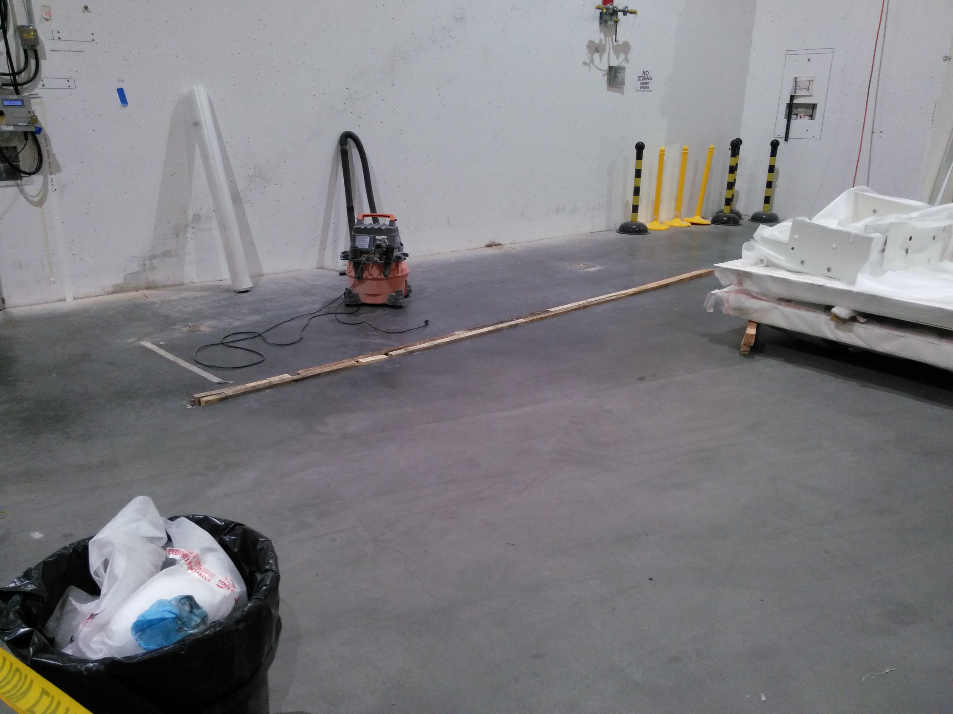
Construction begins on BMM. Hutch panels have been delivered, hutch boundaries are marked in ink on the floors, and door slots have been ground into the concrete.
| Construction begins | Slot for 6BM-B door | Slot for 6BM-A door | Parts for the 6BM hutches | 6BM-A wall panels | 4BM-B roof panels (ours will be similar) |
 |
 |
 |
 |
 |
 |